
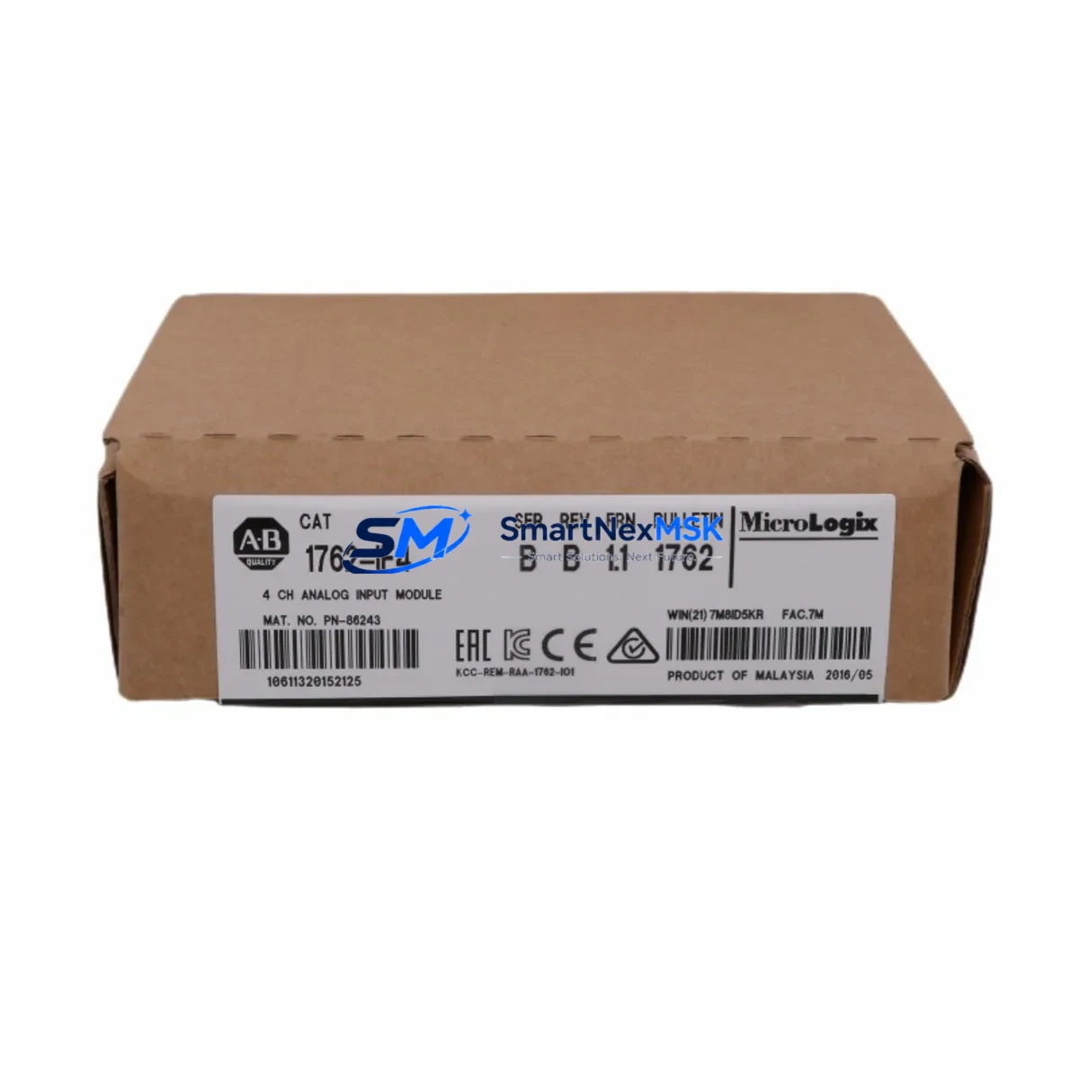
Allen-Bradley 1762-IF4 Retrofit-Ready Analog Input Module for MicroLogix Control Systems
The Allen-Bradley 1762-IF4 is a 4-channel analog input expansion module designed for the MicroLogix 1762 I/O platform, offering seamless compatibility with MicroLogix 1100, MicroLogix 1200, and MicroLogix 1400 controllers. For facilities managing aging automation infrastructure, the 1762-IF4 represents one of the most reliable and cost-effective paths to restoring or upgrading analog signal acquisition without requiring a full control system overhaul. Whether you are replacing a failed module on a running production line or planning a phased retrofit of legacy PLC hardware, the 1762-IF4 delivers the wiring compatibility, signal accuracy, and platform integration that engineers depend on.
Upgrade Compatibility Table
| Parameter | Specification / Detail |
|---|---|
| SKU / Part Number | 1762-IF4 |
| Brand / Manufacturer | Allen-Bradley (Rockwell Automation) |
| Series | MicroLogix 1762 Expansion I/O |
| Compatible Controllers | MicroLogix 1100, MicroLogix 1200, MicroLogix 1400 |
| Input Channels | 4 Analog Input Channels |
| Input Signal Types | Voltage (0–10 VDC, ±10 VDC) / Current (4–20 mA, 0–20 mA) |
| Resolution | 12-bit (0–4095 counts) |
| Backplane Interface | MicroLogix 1762 expansion bus (right-side connector) |
| Installation Method | DIN rail or panel mount; direct snap-on to MicroLogix base unit or 1762 expansion chain |
| Wiring Compatibility | Drop-in replacement for existing 1762-IF4 wiring; no terminal rewiring required for like-for-like swap |
| Power Consumption | Supplied via MicroLogix expansion bus; verify controller power budget before adding modules |
| Operating Temperature | 0°C to 60°C (32°F to 140°F) |
| Retrofit Recommendation | Verify RSLogix 500 program file for correct I/O configuration map before hot-swap or cold replacement |
| Commissioning Notes | Re-download program after module swap; confirm channel scaling and filter settings in RSLogix 500 |
| Warranty | 12-Month Warranty — All units ship tested and verified |
Retrofit Planning for Existing Automation Systems
Replacing or upgrading the 1762-IF4 within an existing MicroLogix control system requires a structured approach to avoid unplanned downtime and configuration errors. The first step is to audit the current I/O configuration in RSLogix 500, confirming the module’s slot address, channel assignments, and scaling parameters. Because the 1762-IF4 connects to the MicroLogix controller via the 1762 expansion bus, engineers must also verify that the total expansion chain does not exceed the controller’s maximum I/O module count — typically up to 6 expansion modules for MicroLogix 1400 and fewer for MicroLogix 1100 and 1200.
Power budget verification is equally critical. The MicroLogix 1100 and 1200 base units supply limited backplane current, and adding or replacing modules — including the 1762-IF4 alongside digital expansion modules such as the 1762-IQ16 (16-channel DC input) or 1762-OW16 (16-channel relay output) — can approach the controller’s power capacity. Always cross-reference the power consumption table in the MicroLogix 1400 installation manual (Publication 1762-IN001) before finalizing the expansion configuration.
For facilities transitioning from older MicroLogix 1000 or SLC 500 platforms, the 1762-IF4 is often part of a broader migration strategy. In these cases, the 1762-IF4 is paired with a MicroLogix 1400 controller (1766-L32BXBA or 1766-L32AWA) to replicate analog input functionality previously handled by SLC 500 analog modules such as the 1746-NI4 or 1746-NI8. The wiring from field transmitters — pressure transducers, flow meters, temperature sensors — can typically be re-terminated directly to the 1762-IF4 terminal block without signal conditioning changes, provided the transmitter output range matches the module’s configured input type.
Communication continuity is another key consideration. MicroLogix systems using DF1 serial communication via the 1761-CBL-PM02 programming cable or Ethernet connectivity through the 1761-NET-ENI Ethernet interface adapter must remain operational during the retrofit window. Ensure the RSLogix 500 project file is backed up and the communication path is re-established immediately after module replacement. For systems using DeviceNet or DH-485 networks, confirm that the 1762-IF4 replacement does not disrupt the network node addressing or scan list configuration.
Where the retrofit involves upgrading from a MicroLogix 1200 to a MicroLogix 1400, the 1762-IF4 modules from the original system are fully reusable — the expansion bus pinout and protocol are identical across the MicroLogix 1762 I/O family. This compatibility significantly reduces spare parts cost and simplifies the upgrade path. Pair the retained 1762-IF4 modules with a new 1762-OA8 (8-channel AC output) or 1762-IQ8 (8-channel DC input) to complete the I/O expansion without purchasing an entirely new I/O set.
Downtime Control During System Migration
Minimizing control system downtime during a 1762-IF4 replacement or MicroLogix retrofit requires preparation that begins well before the maintenance window. The most effective strategy is to pre-configure and bench-test the replacement module before taking the system offline. Using a spare MicroLogix 1400 or 1200 controller on the workbench, load the existing RSLogix 500 program, insert the new 1762-IF4, and verify that all four analog input channels read correctly with a signal simulator or calibrated current source set to 4–20 mA.
During the live replacement, follow a structured sequence: power down the controller, disconnect field wiring from the existing module’s terminal block (photograph or label each wire before removal), remove the failed 1762-IF4 from the expansion chain, install the replacement unit, reconnect field wiring in the original configuration, and restore power. The MicroLogix controller will automatically detect the new module on the expansion bus and resume normal operation if the program’s I/O configuration matches the physical hardware. No program re-download is required in most like-for-like swap scenarios, though it is best practice to force a program verify in RSLogix 500 to confirm no configuration drift has occurred.
For planned upgrades — such as migrating from a MicroLogix 1200 to a MicroLogix 1400 — schedule the cutover during a planned production shutdown. Pre-wire the new controller and I/O modules in a temporary panel, perform a full functional test with simulated I/O signals, and execute the physical cutover by transferring field wiring terminal by terminal. This approach keeps the original system intact as a fallback until the new system is fully validated, protecting production continuity and reducing the risk of extended unplanned downtime.
All 1762-IF4 units supplied by SMARTNEXMSK are shipped pre-tested and verified against factory specifications. Each unit undergoes functional inspection prior to dispatch, and is covered by a 12-month warranty from the date of delivery. In-stock inventory ensures fast lead times, supporting urgent replacement scenarios where production continuity depends on rapid spare parts availability.
Retrofit Support FAQ
Q1: Is the 1762-IF4 a direct drop-in replacement for a failed unit in my existing MicroLogix system?
Yes. The 1762-IF4 is a direct replacement for any existing 1762-IF4 module in a MicroLogix 1100, 1200, or 1400 expansion chain. The backplane connector, terminal block layout, and RSLogix 500 I/O configuration map are identical, so no program changes or wiring modifications are required for a like-for-like swap. Simply power down, replace the module, restore power, and verify operation.
Q2: Can the 1762-IF4 be used to replace analog input modules from older SLC 500 or MicroLogix 1000 systems?
The 1762-IF4 is not a direct plug-in replacement for SLC 500 analog modules (such as the 1746-NI4) due to differences in backplane architecture. However, it is the correct analog input module for any MicroLogix 1762 I/O-based system. When migrating from SLC 500 to MicroLogix 1400, field wiring from existing analog transmitters can typically be re-terminated to the 1762-IF4 terminal block with minimal adaptation, provided signal ranges are compatible.
Q3: What commissioning steps are required after installing a replacement 1762-IF4?
After installation, power up the controller and open the RSLogix 500 project. Navigate to the I/O configuration and verify that the 1762-IF4 is recognized in the correct slot. Check channel scaling parameters (engineering units, filter settings, input type selection) to confirm they match the original configuration. Use the RSLogix 500 data monitor to verify live analog readings from each channel against known field signal values. If any channel reads incorrectly, confirm the input type jumper or software configuration matches the field transmitter output (voltage vs. current).
Q4: What warranty and testing does SMARTNEXMSK provide with the 1762-IF4?
Every 1762-IF4 unit supplied by SMARTNEXMSK is covered by a 12-month warranty from the date of shipment. All units are functionally tested prior to dispatch to verify analog input accuracy, backplane communication, and channel integrity. In the event of a warranty claim, SMARTNEXMSK provides replacement or repair support. Long-term supply continuity is maintained through managed inventory, ensuring availability for ongoing maintenance and spare parts programs.
© 2026 SMARTNEXMSK. All rights reserved.
Original Source: https://smartnexmsk.com
Contact: [email protected] | +86 18259474341



