
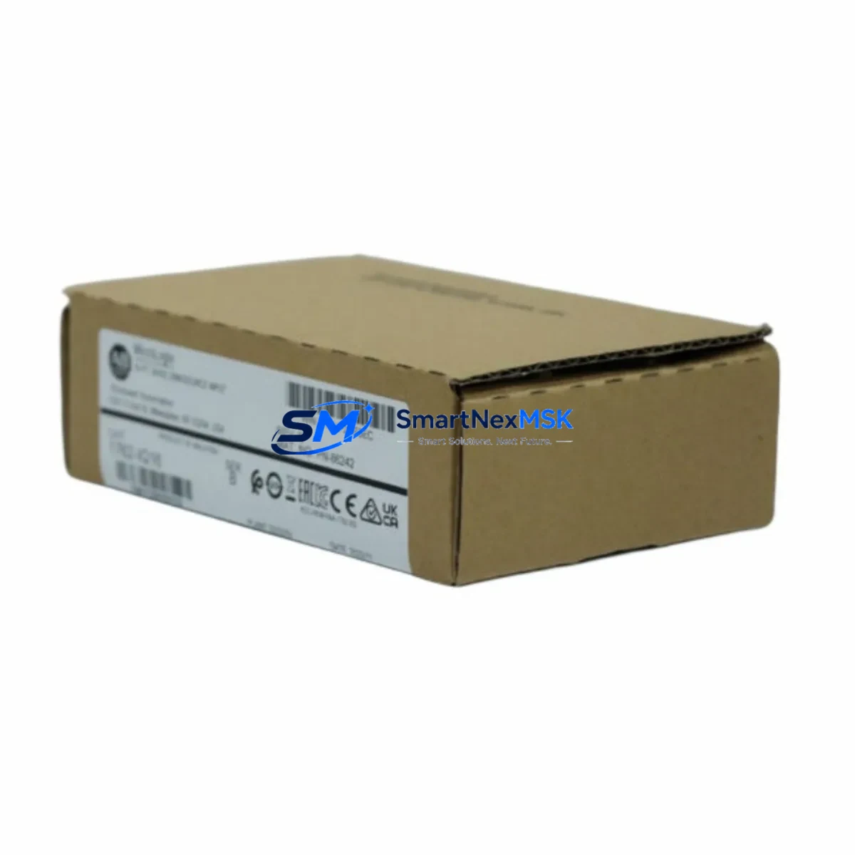
Allen-Bradley 1762-IQ16 Spare for MicroLogix Automation: Spare Replacement & Industrial Downtime Risk Control
The Allen-Bradley 1762-IQ16 is a 16-point, 24V DC digital input expansion module designed for the MicroLogix 1200 and MicroLogix 1500 programmable controller platforms. As a core field I/O component in distributed control architectures, the 1762-IQ16 is responsible for reading discrete field signals — from pushbuttons, proximity sensors, limit switches, and photoelectric sensors — and delivering them to the controller’s logic engine. When this module fails or degrades, the entire associated control loop is compromised, triggering unplanned downtime and production loss.
At SMARTNEXMSK, we supply original Allen-Bradley 1762-IQ16 modules sourced through verified industrial channels. Every unit undergoes functional testing prior to dispatch, and is backed by a 12-month warranty. Our inventory is maintained to support both emergency replacement orders and planned maintenance procurement cycles.
Spare Maintenance Table
| Parameter | Specification |
|---|---|
| Part Number / SKU | 1762-IQ16 |
| Brand / Manufacturer | Allen-Bradley (Rockwell Automation) |
| Series Compatibility | MicroLogix 1200, MicroLogix 1500 |
| Module Type | Digital Input (DC) |
| Number of Input Points | 16 Points |
| Input Voltage | 24V DC (Sink/Source) |
| Input Current (per point) | Approx. 7 mA @ 24V DC |
| ON State Voltage Range | 15–26.4V DC |
| OFF State Voltage Range | 0–5V DC |
| Isolation | Optical isolation between field and logic side |
| Backplane Connection | 1762 Expansion Bus (right-side expansion) |
| Operating Temperature | 0°C to 55°C (32°F to 131°F) |
| Storage Temperature | -40°C to 85°C |
| Relative Humidity | 5–95% non-condensing |
| Enclosure Rating | IP20 (panel-mount, open type) |
| Dimensions (H × W × D) | Approx. 90 × 40 × 87 mm |
| Weight | Approx. 250 g |
| Country of Origin | United States |
| Certifications | UL, CE, CSA (per Rockwell Automation documentation) |
| Warranty | 12 Months (SMARTNEXMSK) |
| Condition | Original, New or Tested Surplus |
| Lead Time | In-stock: ships within 1–3 business days |
Maintenance Planning for Continuous Operation
When a 1762-IQ16 digital input module is flagged during a control cabinet inspection or fault diagnostic, experienced maintenance engineers know that the module itself is rarely the only component requiring attention. A thorough site assessment should extend to the entire input signal chain and the surrounding MicroLogix expansion system.
Begin by verifying the 24V DC power supply feeding the input circuit — a degraded or undersized power supply (such as the 1762-PA8 or equivalent 24VDC rail supply) can cause intermittent input faults that mimic module failure. Check the 1762 expansion cable connecting the module to the MicroLogix base unit; a damaged or loose expansion connector is a common root cause of communication errors between the controller and the I/O module.
Inspect the terminal block wiring at the module’s field-side connector. Loose terminals, corroded contacts, or undersized wire gauge can introduce signal noise or open-circuit conditions on individual input channels. If the installation uses signal isolators between field sensors and the 1762-IQ16 input terminals, verify that the isolator output voltage levels are within the module’s ON-state threshold range (15–26.4V DC).
For systems where the 1762-IQ16 is paired with output modules such as the 1762-OW16 (relay output) or 1762-OB16 (transistor output), cross-check the output-side relay contacts and fuse protection. A blown fuse on the output side can create misleading diagnostic patterns that appear as input faults. Similarly, if the MicroLogix system includes a 1762-IF4 analog input module or 1762-OF4 analog output module in the same expansion rack, confirm that the backplane bus is not overloaded and that all modules are firmly seated.
Communication health should also be assessed. If the MicroLogix 1200 or 1500 controller uses an RS-232 or RS-485 communication module (such as the 1761-NET-AIC or 1763-NC01) for SCADA or HMI connectivity, verify that the communication link remains stable after module replacement. An HMI panel — such as a PanelView Component or third-party operator terminal — should be tested to confirm that all I/O status indicators update correctly following the swap.
For aging MicroLogix installations, consider stocking a 1762-IQ16 as a direct cold-standby spare alongside the controller’s CPU unit (1762-L24BWA or 1762-L40BWA) and the system’s 24V DC power supply. This three-component spare kit covers the most common failure points in a MicroLogix 1200 panel and can reduce mean time to repair (MTTR) from hours to under 30 minutes.
Site Replacement Workflow
Step 1 — Isolate and de-energize. Before removing the 1762-IQ16, isolate the control panel from the field power supply. Switch off the 24V DC input power rail and confirm zero voltage at the module terminals using a calibrated multimeter.
Step 2 — Document wiring. Photograph or record the terminal wiring layout on the existing module. The 1762-IQ16 uses a removable terminal block, which simplifies transfer to the replacement unit without rewiring individual conductors.
Step 3 — Remove the faulty module. Disconnect the expansion bus connector on the left side of the module (if applicable) and slide the module off the DIN rail or panel mount. The 1762 series uses a tool-free latch mechanism for quick removal.
Step 4 — Install the replacement 1762-IQ16. Seat the new module onto the expansion bus, ensuring the backplane connector is fully engaged. Reattach the terminal block. The 1762-IQ16 is a direct drop-in replacement — no firmware changes or controller re-configuration are required when replacing with an identical part number.
Step 5 — Re-energize and verify. Restore 24V DC power and observe the module’s LED status indicators. All 16 input LEDs should reflect the current field signal states. Use RSLogix 500 or Studio 5000 Logix Designer (in monitor mode) to confirm that all input bits are reading correctly in the controller’s I/O image table.
Step 6 — Functional test. Cycle each field device connected to the 1762-IQ16 inputs and verify correct state changes in the controller program. Document the replacement in the panel’s maintenance log and update the spare parts inventory record.
Spare Parts Support FAQ
Q1: Is the 1762-IQ16 still available as a new original part, or only as surplus?
The 1762-IQ16 has been in the Allen-Bradley MicroLogix 1200/1500 product family for many years and may be approaching or past its active production lifecycle. SMARTNEXMSK supplies both new original stock (where available) and fully tested surplus units. All units are inspected and function-tested before shipment. The 12-month warranty applies equally to both supply types.
Q2: How do I verify compatibility before ordering?
The 1762-IQ16 is compatible with all MicroLogix 1200 and MicroLogix 1500 base units that support the 1762 expansion bus. Confirm your base unit part number (e.g., 1762-L24BWA, 1762-L40BWA, 1763-L16BWA) and verify that your expansion slot count does not exceed the controller’s maximum I/O expansion limit. Contact [email protected] with your system configuration for pre-order compatibility confirmation.
Q3: What testing is performed before shipment?
Each 1762-IQ16 unit is powered up and tested for correct input channel response across all 16 points. Backplane communication integrity and LED indicator function are verified. Units that do not pass full functional testing are not dispatched. A test report is available upon request for critical maintenance applications.
Q4: What is the recommended spare parts stocking strategy for MicroLogix systems?
For facilities operating multiple MicroLogix 1200 or 1500 panels, we recommend maintaining at least one 1762-IQ16 per panel type in your on-site spare parts store. For high-criticality lines, a cold-standby kit comprising the 1762-IQ16, the matched output module (1762-OW16 or 1762-OB16), and the controller CPU is the industry-standard approach to minimizing unplanned downtime. SMARTNEXMSK can support blanket orders and scheduled replenishment agreements for long-term supply continuity.
© 2026 SMARTNEXMSK. All rights reserved.
Original Source: https://smartnexmsk.com
Contact: [email protected] | +86 18259474341



