
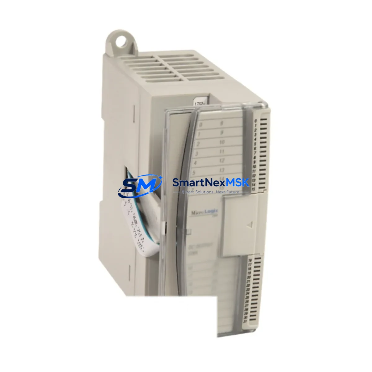
Allen-Bradley 1762-IR4 Spare for MicroLogix Automation: Spare Replacement & Industrial Downtime Risk Control
The Allen-Bradley 1762-IR4 is a 4-channel RTD (Resistance Temperature Detector) input module designed for the MicroLogix 1100 and MicroLogix 1400 expansion I/O system. As a critical signal acquisition component in temperature-sensitive process control loops, the 1762-IR4 is routinely found in food processing lines, HVAC control panels, chemical batch systems, and general-purpose industrial automation cabinets. When this module fails or degrades, the entire temperature monitoring loop is compromised — triggering process shutdowns, safety interlocks, or uncontrolled batch deviations. Maintaining a certified original spare on the shelf is the most effective strategy to minimize mean time to repair (MTTR) and protect production continuity.
At SMARTNEXMSK, every 1762-IR4 unit is sourced as an original Allen-Bradley component, individually tested prior to dispatch, and backed by a 12-month warranty. Our inventory is maintained to support both planned maintenance cycles and emergency replacement scenarios, with fast international shipping to reduce logistics lead time in critical situations.
Spare Maintenance Table
| Parameter | Specification |
|---|---|
| Part Number | 1762-IR4 |
| Brand | Allen-Bradley (Rockwell Automation) |
| Series | MicroLogix Expansion I/O |
| Compatible Controllers | MicroLogix 1100 (1763-L16xxx), MicroLogix 1400 (1766-L32xxx) |
| Input Channels | 4 RTD channels (individually configurable) |
| Supported RTD Types | 100Ω Platinum (385 & 392), 200Ω Platinum, 500Ω Platinum, 1000Ω Platinum, 10Ω Copper, 120Ω Nickel |
| Input Resolution | 0.1°C / 0.1°F |
| Operating Temperature | 0°C to 60°C (32°F to 140°F) |
| Storage Temperature | -40°C to 85°C |
| Power Consumption | 80 mA @ 5 VDC (from expansion bus) |
| Isolation | Channel-to-channel and channel-to-backplane isolation |
| Mounting | DIN rail or panel mount via MicroLogix expansion bus connector |
| Enclosure Rating | Open type — requires installation in IP54 or better enclosure |
| Certifications | UL, CE, C-Tick |
| Origin | USA |
| Warranty | 12 Months (SMARTNEXMSK) |
| Condition | Original, new or tested-serviceable |
| Shipping | Tested before dispatch; international express available |
Maintenance Planning for Continuous Operation
When a maintenance or procurement engineer schedules replacement of the 1762-IR4, the inspection scope should extend beyond the module itself. A thorough control cabinet audit during the same maintenance window significantly reduces the risk of repeat failures and unplanned downtime.
Start with the MicroLogix controller base unit — the 1763-L16BWA or 1766-L32BWAA — and verify firmware version compatibility with the replacement module. Confirm that the expansion bus ribbon cable connecting the 1762-IR4 to the controller or adjacent expansion module (such as a 1762-OW8 relay output module or 1762-IQ8 digital input module) is free of corrosion, cracking, or loose seating. These ribbon connectors are a common failure point in high-vibration environments and are inexpensive to replace proactively.
Inspect the 24 VDC power supply feeding the MicroLogix system — typically a 1606-XLP or equivalent Allen-Bradley power supply — for output voltage stability and ripple. An unstable supply rail can cause intermittent RTD reading errors that mimic module failure. Check terminal blocks on the RTD wiring side: loose or oxidized connections on the 3-wire or 4-wire RTD circuits are a leading cause of out-of-range or drifting temperature readings.
If the cabinet includes a 1762-OA8 AC output module or 1762-OB16 DC output module driving heating elements or cooling fans based on the RTD feedback loop, verify those output channels are functioning correctly before closing the maintenance work order. A failed output module can mask a correctly functioning 1762-IR4 by preventing the control response from executing.
For systems with communication requirements, check the 1761-NET-ENI Ethernet interface or 1747-KFC15 ControlNet adapter if the MicroLogix is integrated into a supervisory SCADA or DCS network. Communication faults during a module swap can trigger false alarms at the HMI level — typically a PanelView 600 or PanelView Plus 700 — and should be cleared after the replacement is confirmed stable.
Finally, if the installation includes signal isolators between the RTD field devices and the 1762-IR4 input terminals, verify that the isolator output range matches the module’s configured input type. Mismatched signal conditioning is a frequently overlooked source of calibration drift after a module replacement.
Site Replacement Workflow
Step 1 — Pre-replacement verification: Download and save the current MicroLogix program using RSLogix 500 or Studio 5000 Logix Designer. Record all I/O configuration settings for the 1762-IR4 slot, including RTD type, temperature units, filter frequency, and fault mode behavior.
Step 2 — Safe isolation: Place the MicroLogix controller in Program mode via the keyswitch or RSLogix 500 online connection. De-energize the expansion bus by powering down the controller base unit. Do not hot-swap MicroLogix expansion modules — this can corrupt the I/O table and damage the backplane connector.
Step 3 — Physical replacement: Disconnect RTD field wiring from the terminal block, noting wire positions for 3-wire or 4-wire configurations. Remove the 1762-IR4 by releasing the DIN rail latch and disconnecting the expansion bus connector. Install the replacement module, reconnect the expansion bus, and re-terminate the RTD field wiring per the original wiring diagram.
Step 4 — Configuration restore: Power up the system and go online with RSLogix 500. Verify that the replacement 1762-IR4 is recognized in the correct slot. Restore the I/O configuration if required. Confirm that all four RTD channels are reading within expected range before returning the controller to Run mode.
Step 5 — Functional test: Simulate or verify live RTD readings against a calibrated reference. Confirm that downstream control outputs (heating, cooling, alarm) respond correctly to temperature changes. Log the replacement in the maintenance management system (CMMS) with the new module serial number and installation date.
This workflow is compatible with both direct 1762-IR4 replacements and upgrades from legacy Allen-Bradley SLC 500 analog input modules where a MicroLogix migration has been performed. The 1762-IR4 provides a cost-effective path to extend the service life of existing MicroLogix-based control systems without requiring a full PLC platform migration.
Spare Parts Support FAQ
Q1: Is the 1762-IR4 still available as a new original part, or only as a refurbished unit?
SMARTNEXMSK maintains stock of original Allen-Bradley 1762-IR4 modules. Each unit is individually inspected and tested before shipment. Where new stock is available, it is clearly indicated. Tested-serviceable units are fully functional and covered by the same 12-month warranty.
Q2: How do I confirm compatibility between the 1762-IR4 and my specific MicroLogix controller revision?
The 1762-IR4 is compatible with all hardware revisions of the MicroLogix 1100 and MicroLogix 1400. Compatibility is determined by the expansion I/O bus standard, not by controller firmware revision. If you are integrating the module into a mixed expansion rack alongside other 1762-series modules, slot position does not affect functionality — any slot in the expansion chain is valid.
Q3: What testing is performed before the 1762-IR4 is shipped?
Each unit undergoes power-on functional testing with live RTD simulation across all four channels. Output data is verified against factory specification tolerances. Units that do not meet specification are not dispatched. A test report is available upon request for critical infrastructure applications.
Q4: What does the 12-month warranty cover, and what is the replacement process?
The 12-month warranty covers manufacturing defects and functional failures under normal operating conditions. If a unit fails within the warranty period, SMARTNEXMSK will provide a replacement unit after fault confirmation. Customers are asked to provide a brief fault description and, where possible, a photo of the installation environment. Warranty replacements are processed within 5 business days of fault confirmation.
© 2026 SMARTNEXMSK. All rights reserved.
Original Source: https://smartnexmsk.com
Contact: [email protected] | +86 18259474341



