
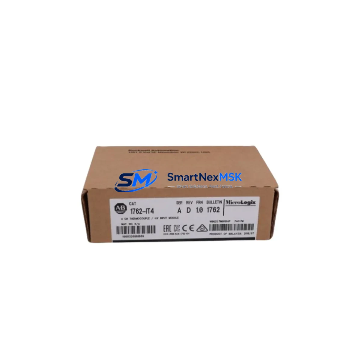
Allen-Bradley 1762-IT4 Maintenance-Ready Spare MicroLogix
The Allen-Bradley 1762-IT4 is a 4-channel thermocouple and RTD analog input module designed for MicroLogix 1100 and MicroLogix 1400 control systems. As a critical measurement front-end in temperature-sensitive industrial processes — including furnace control, HVAC automation, food processing lines, and chemical reactor monitoring — the 1762-IT4 is one of the highest-priority spare parts in any MicroLogix-based control cabinet. Unplanned failure of this module results in immediate loss of temperature feedback, triggering process shutdowns, safety interlocks, and costly unplanned downtime.
Sourced as an original Allen-Bradley component, this spare is tested prior to shipment, covered by a 12-month warranty, and available for fast worldwide dispatch. Whether you are building a preventive maintenance stock, responding to an emergency replacement, or extending the operational life of an aging MicroLogix system, the 1762-IT4 spare from SMARTNEXMSK provides the compatibility assurance and supply reliability that maintenance and procurement engineers require.
Spare Maintenance Table
| Part Number / SKU | 1762-IT4 |
| Brand | Allen-Bradley (Rockwell Automation) |
| Series Compatibility | MicroLogix 1100 (1763-L16xxx), MicroLogix 1400 (1766-L32xxx) |
| Module Type | Analog Input — Thermocouple / RTD |
| Input Channels | 4 differential analog input channels |
| Sensor Types Supported | J, K, E, T, R, S, B thermocouples; PT100, PT1000, Ni120 RTDs |
| Resolution | 16-bit |
| Input Range | -270°C to +1820°C (type-dependent) |
| Bus Interface | MicroLogix 1762 expansion bus |
| Power Consumption | 85 mA @ 5 VDC (from expansion bus) |
| Operating Temperature | 0°C to 60°C |
| Certifications | UL, CE, cUL |
| Origin | United States |
| Condition | Original, New |
| Warranty | 12 Months — SMARTNEXMSK Quality Guarantee |
| Pre-Shipment Testing | Functional verification performed before dispatch |
| Shipping | Worldwide express; DHL / FedEx / UPS available |
Maintenance Planning for Continuous Operation
When a 1762-IT4 module is flagged for replacement during a scheduled inspection or emergency callout, experienced maintenance engineers treat the event as a trigger for a broader control cabinet audit. The 1762-IT4 sits on the MicroLogix 1762 expansion bus alongside other I/O modules, and its failure — or the wiring conditions that caused it — can affect adjacent components in the same rack.
Start by verifying the 1762-L24BWA or 1763-L16BWA base unit power supply rail: a sagging 5 VDC bus is a common root cause of analog module faults and should be measured before installing the replacement. Inspect the 1762-OW8 relay output module and 1762-IQ8 digital input module in the same expansion chain — loose bus connectors cause intermittent faults across all expansion slots. Check the 1762-IF4 analog voltage/current input module if the cabinet also handles 4–20 mA process signals; a shared wiring harness fault can affect both analog modules simultaneously.
Thermocouple field wiring should be inspected at the terminal block level. Replace any corroded or loose connections on the 1492-CABLE series field wiring accessories or equivalent terminal strip assemblies. Cold junction compensation errors are frequently traced to poor shield grounding rather than module failure itself. If the system uses a 1762-OA8 AC output module to drive heating elements, verify contactor coil integrity and check for voltage spikes that may have stressed the analog input circuitry.
For MicroLogix systems with communication requirements, inspect the 1761-NET-ENI Ethernet interface or 1761-NET-AIC Advanced Interface Converter if remote monitoring of temperature data is part of the SCADA architecture. A failed analog input module that goes undetected in a networked system often indicates a gap in alarm configuration — review the RSLogix 500 program’s analog alarm rungs as part of the corrective action. If an HMI panel such as the PanelView Component C400 or C600 is used for local temperature display, confirm that the data table mappings remain intact after module replacement and firmware re-initialization.
Finally, review the 1762-IQ16 digital input module and any associated signal isolators or loop-powered barriers in the thermocouple circuit. In high-noise industrial environments — particularly near variable frequency drives or large motor starters — signal isolation is essential to protect the 1762-IT4’s high-resolution 16-bit inputs from common-mode interference. Stocking a spare 1762-IF2OF2 combination analog I/O module alongside the 1762-IT4 provides additional coverage for mixed analog architectures common in MicroLogix 1400 installations.
Site Replacement Workflow
Step 1 — Isolation and Safety: Place the MicroLogix controller in Program mode via RSLogix 500 or the keyswitch. De-energize the expansion bus by powering down the base unit. Do not hot-swap 1762 expansion modules — the bus does not support live insertion.
Step 2 — Module Removal: Disconnect all thermocouple/RTD field wiring from the 1762-IT4 terminal block, labeling each wire by channel number and sensor type. Release the DIN rail locking tab and slide the module free from the expansion bus connector.
Step 3 — Replacement Installation: Seat the new 1762-IT4 firmly onto the expansion bus connector and secure the DIN rail latch. Reconnect field wiring per the original channel assignments. Verify shield grounding continuity.
Step 4 — Configuration Verification: Power up the base unit and open RSLogix 500. Confirm the I/O configuration tree recognizes the 1762-IT4 at the correct slot address. Verify sensor type configuration in the module’s configuration file (IIN/IOUT data file). No re-programming is required if the replacement module is the same catalog number.
Step 5 — Functional Test: Apply known temperature references to each channel and verify the data table values match expected engineering units. Check analog alarm setpoints and confirm SCADA or HMI displays are updating correctly before returning the system to Run mode.
This workflow minimizes downtime to under 30 minutes for a prepared maintenance team with a verified spare on hand — reinforcing the value of proactive spare parts inventory management for MicroLogix-based automation systems.
Spare Parts Support FAQ
Q1: Is this 1762-IT4 compatible with both MicroLogix 1100 and MicroLogix 1400?
Yes. The 1762-IT4 is fully compatible with all MicroLogix 1100 (1763-L16xxx series) and MicroLogix 1400 (1766-L32xxx series) base units. It connects via the standard 1762 expansion bus and requires no hardware modification. Confirm your base unit’s expansion slot count before ordering to ensure sufficient bus capacity.
Q2: What pre-shipment testing is performed on this spare?
Each 1762-IT4 unit undergoes functional verification prior to dispatch, including power-on self-test confirmation and channel continuity checks. Units that do not pass testing are not shipped. A 12-month warranty covers defects in materials and workmanship from the date of receipt.
Q3: Can this module replace an older revision of the 1762-IT4?
Yes. Allen-Bradley maintains backward compatibility across hardware revisions of the 1762-IT4. The replacement module will operate with existing RSLogix 500 programs without modification, provided the catalog number matches. If your system uses a very early firmware revision of the MicroLogix base unit, a firmware update may be recommended — consult the Rockwell Automation compatibility matrix or contact our technical team.
Q4: What is the recommended spare parts stocking strategy for MicroLogix systems?
For critical production lines, maintain at minimum one 1762-IT4 per installed system. For facilities with multiple MicroLogix installations, a shared pool of two to three units is typically sufficient. Pair the 1762-IT4 spare with a 1762-IF4 analog input module and a set of replacement thermocouple terminal blocks to cover the most common analog input failure scenarios. SMARTNEXMSK supports long-term supply agreements for customers requiring guaranteed stock availability.
© 2026 SMARTNEXMSK. All rights reserved.
Original Source: https://smartnexmsk.com
Contact: [email protected] | +86 18259474341



