
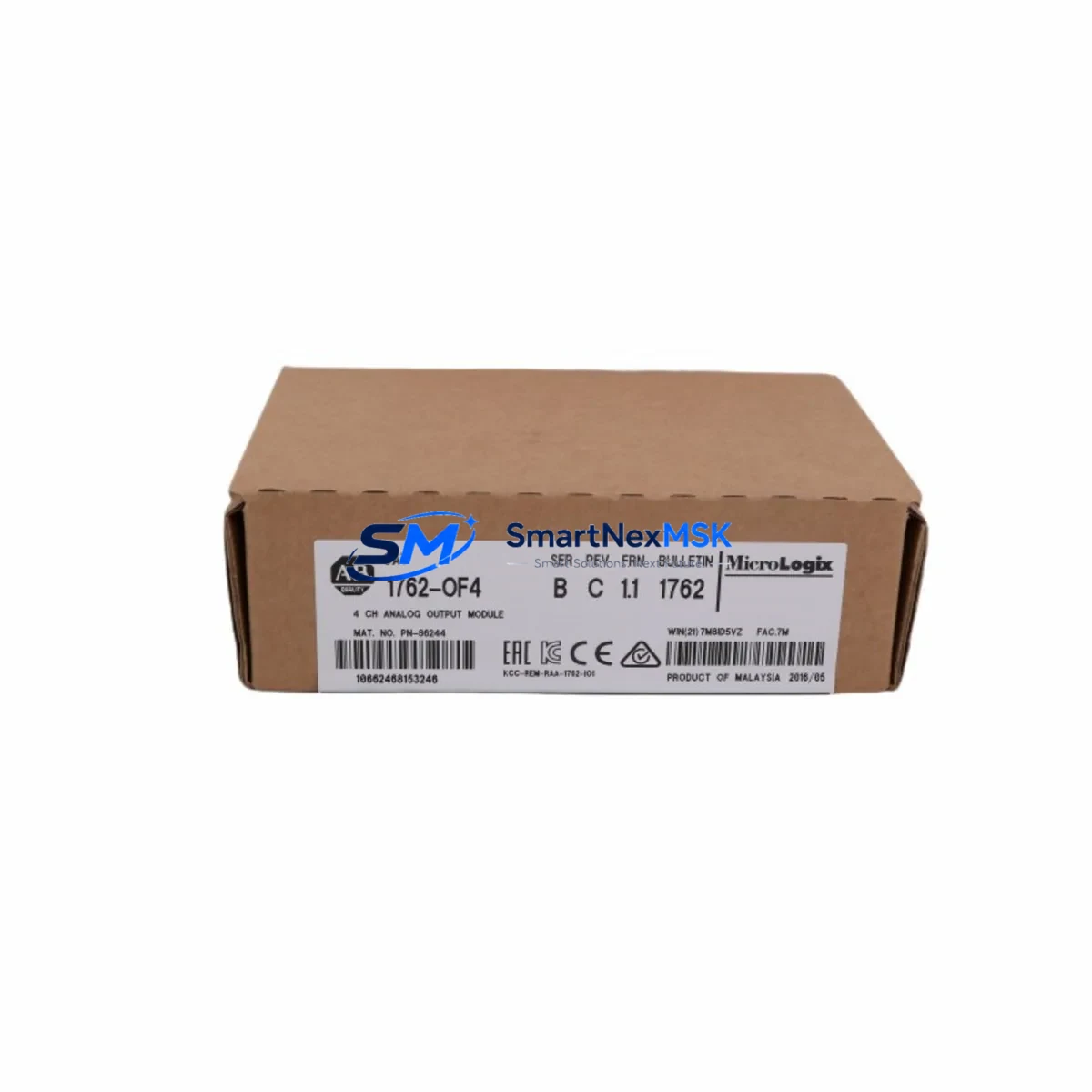
Allen-Bradley 1762-OF4 Retrofit-Ready Analog Output Module: Compatible Upgrade for MicroLogix Control Systems
The Allen-Bradley 1762-OF4 is a 4-channel analog output module designed for the MicroLogix Expansion I/O platform, delivering reliable voltage and current signal outputs for process control, drive speed reference, and valve positioning applications. As legacy MicroLogix 1100 and MicroLogix 1400 systems age into end-of-life cycles, the 1762-OF4 remains one of the most sought-after retrofit components for engineers tasked with maintaining production continuity without full system replacement.
Whether you are replacing a failed output module on an existing control cabinet, expanding analog capacity on a running line, or migrating from an older SLC 500 platform to a MicroLogix-based architecture, the 1762-OF4 provides a proven, drop-in compatible solution. Each unit shipped by SMARTNEXMSK is functionally tested, serialized, and covered by a 12-month warranty from the date of delivery.
Upgrade Compatibility Table
| Parameter | Details |
|---|---|
| Compatible Controllers | MicroLogix 1100 (1763-L16xxx), MicroLogix 1400 (1766-L32xxx) |
| Expansion Bus Interface | 1762 Series I/O Expansion Bus (right-side connector) |
| Output Channels | 4 channels — configurable per channel as 0–10 VDC or 4–20 mA |
| Resolution | 12-bit (0–4095 counts) |
| Power Consumption | 85 mA @ 5 VDC (from expansion bus); verify backplane current budget before installation |
| Terminal Wiring | Removable screw-terminal block; 14–22 AWG wire range |
| Module Addressing | Auto-addressed by slot position on expansion bus; configure output file O:x.0–O:x.3 in RSLogix 500/Micro |
| Communication Protocol | Proprietary 1762 expansion bus; no separate network configuration required |
| Replacement Compatibility | Direct drop-in for existing 1762-OF4 installations; verify firmware revision of host controller |
| Commissioning Notes | Calibration via RSLogix 500 Micro; verify output scaling in ladder logic after installation |
| Warranty | 12 months from shipment date — covers functional defects under normal operating conditions |
Retrofit Planning for Existing Automation Systems
Integrating the 1762-OF4 into an existing control system requires a structured approach to avoid unplanned downtime and configuration errors. Begin by auditing the current expansion bus configuration. The MicroLogix 1100 and 1400 controllers support up to 6 expansion modules on the 1762 bus, and the total backplane current draw — including the 1762-OF4 at 85 mA — must remain within the controller’s rated supply capacity. If the existing cabinet already runs a 1762-IQ16 digital input module, a 1762-OW16 relay output module, and a 1762-IF4 analog input module, the addition of the 1762-OF4 must be validated against the remaining current budget before powering up.
Terminal wiring is a critical step. The 1762-OF4 uses a removable screw-terminal block, which simplifies replacement without disturbing field wiring — provided the original terminal block is retained and re-used. Each channel’s output type (voltage or current) must be set via jumper configuration on the module before installation, and the corresponding ladder logic output file must be scaled to match. Engineers migrating from older SLC 500 analog output modules such as the 1746-NO4I will need to remap output file addresses and adjust scaling constants in the program, as the data file structure differs between platforms.
For systems that include a PanelView 800 or PanelView Component HMI communicating over EtherNet/IP or DF1 serial to the MicroLogix 1400, analog output tag bindings in the HMI project must be verified after any module slot change. If the 1762-OF4 is inserted into a different slot position than the original module, the output file address (O:x) will shift, and all HMI numeric display and analog bar graph objects referencing those tags must be updated accordingly.
In systems where a 1761-NET-ENI Ethernet interface or a 1761-CBL-PM02 programming cable is used for remote access and program backup, ensure that a full program upload is performed from the controller before beginning any hardware swap. Store the .RSS or .MED project file in a version-controlled location. This protects the original ladder logic, including any PID loop tuning parameters tied to the analog output channels, from being lost during the retrofit process.
If the retrofit involves migrating from a MicroLogix 1000 or MicroLogix 1200 platform — neither of which supports the 1762 expansion bus — a controller upgrade to the MicroLogix 1100 or 1400 is required before the 1762-OF4 can be installed. In such cases, the 1762-A10 10-slot expansion rack or individual snap-together 1762 modules can be used to build out the new I/O configuration alongside the upgraded controller.
Downtime Control During System Migration
Minimizing production downtime during a 1762-OF4 replacement or system migration requires preparation before the maintenance window opens. The recommended approach is to pre-configure and bench-test the replacement module offline using a spare MicroLogix controller or a test rack, verifying that all four analog output channels produce the correct signal levels under program control before the unit is brought to the production floor.
During the swap, power down the controller and expansion bus in the correct sequence — disable field power to actuators and drives first, then remove 24 VDC control power, and finally disconnect the expansion bus connector. Re-installation follows the reverse sequence. After power-up, use RSLogix 500 Micro or Studio 5000 Logix Designer (if connected via a gateway) to go online with the controller and verify that the output file data is being written correctly to the new module before re-enabling field devices.
For critical continuous processes where even a brief interruption is unacceptable, consider a parallel commissioning strategy: install the new 1762-OF4 in an adjacent slot (if available), configure it in the program as a shadow output, and verify signal integrity before cutting over. This approach is particularly effective in drive speed reference and PID output applications where an abrupt signal loss could cause process upsets or equipment damage.
SMARTNEXMSK ships all 1762-OF4 units with pre-shipment functional testing documentation. Each module is powered, addressed, and verified across all four output channels before dispatch, reducing the risk of receiving a non-functional unit and extending your maintenance window unnecessarily.
Retrofit Support FAQ
Q: Is the 1762-OF4 a direct replacement for a failed module in my existing MicroLogix 1400 system?
A: Yes, provided the replacement unit is installed in the same slot position on the expansion bus. The MicroLogix 1400 auto-addresses expansion modules by slot, so a same-slot replacement requires no program changes. If the slot position changes, the output file address (O:x) must be updated in the ladder logic and any associated HMI tag bindings.
Q: What wiring changes are needed when replacing a 1762-OF4?
A: The 1762-OF4 uses a removable screw-terminal block. If the original terminal block is intact, it can be unplugged from the failed module and re-inserted into the replacement unit without disturbing field wiring. Verify that the per-channel voltage/current jumper settings on the new module match the original configuration before powering up.
Q: How do I verify compatibility between the 1762-OF4 and my controller firmware version?
A: Connect to the MicroLogix controller using RSLogix 500 Micro and check the controller properties for the installed firmware revision. Refer to Rockwell Automation’s product compatibility matrix (available via the Rockwell Automation Product Compatibility and Download Center) to confirm that your firmware revision supports the 1762-OF4. SMARTNEXMSK’s technical team can assist with compatibility verification prior to order confirmation.
Q: What does the 12-month warranty cover, and what is the claims process?
A: The 12-month warranty covers functional defects under normal operating conditions, including output channel failure, communication errors on the expansion bus, and terminal block defects. It does not cover damage resulting from incorrect wiring, overvoltage, or physical impact. To initiate a warranty claim, contact [email protected] with the order number, module serial number, and a description of the fault. Replacement units are dispatched within 3 business days of claim approval.
© 2026 SMARTNEXMSK. All rights reserved.
Original Source: https://smartnexmsk.com
Contact: [email protected] | +86 18259474341



