
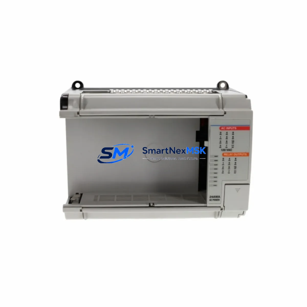
Allen-Bradley 1764-24AWA Retrofit-Ready Base Unit for MicroLogix 1500 Control Systems
The Allen-Bradley 1764-24AWA is a 24-point AC base unit designed for the MicroLogix 1500 programmable controller platform. With 12 discrete AC inputs rated at 120/240VAC and 12 relay outputs, this base unit serves as a direct retrofit replacement for aging or discontinued MicroLogix 1500 installations. Whether you are managing a planned system upgrade, recovering from an unexpected hardware failure, or modernizing a legacy control cabinet, the 1764-24AWA provides a verified drop-in solution that preserves your existing program logic, terminal wiring layout, and backplane communication architecture.
Industrial facilities running MicroLogix 1500 systems often face the challenge of sourcing reliable spare parts as original production runs end. The 1764-24AWA base unit remains one of the most requested components in this series, particularly in applications involving conveyor control, pump station automation, HVAC sequencing, and discrete manufacturing lines. Its compatibility with the 1764-LRP and 1764-LSP processor modules means that field engineers can swap the base unit without reprogramming the controller or reconfiguring the I/O map, provided the processor firmware version is verified prior to installation.
Upgrade Compatibility Table
| Parameter | Details |
|---|---|
| SKU / Part Number | 1764-24AWA |
| Series | MicroLogix 1500 |
| I/O Configuration | 12 Inputs (120/240VAC) / 12 Relay Outputs |
| Compatible Processors | 1764-LRP, 1764-LSP |
| Backplane Interface | MicroLogix 1500 integrated backplane |
| Communication Compatibility | DH-485, RS-232 (DF1), DeviceNet (via 1761-NET-DNI) |
| Replaces / Supersedes | Earlier 1764-24AWA revisions; compatible with Series A and B processors |
| Installation Type | DIN rail or panel mount |
| Retrofit Recommendation | Direct drop-in; verify terminal block wiring and processor firmware before power-up |
| Commissioning Notes | Upload existing program from 1764-LRP before replacement; verify I/O addressing in RSLogix 500 |
| Warranty | 12-Month Warranty included |
Retrofit Planning for Existing Automation Systems
A successful 1764-24AWA retrofit begins well before the replacement unit arrives on site. Engineers should start by documenting the existing terminal block wiring using the original panel drawings or by tracing field wiring directly. The 1764-24AWA uses a removable terminal block, which simplifies the physical swap — the wired terminal block can be transferred directly to the new base unit without disconnecting individual field wires, significantly reducing installation time and the risk of miswiring.
Before removing the existing base unit, connect a programming cable — typically a 1761-CBL-PM02 or 1761-CBL-HM02 — to the RS-232 port on the 1764-LRP or 1764-LSP processor and upload the current ladder logic program using RSLogix 500 or Studio 5000 Logix Designer in compatibility mode. Store the program file with a revision timestamp. If the system uses a 1764-MM1 or 1764-MM2 memory module, verify that the program has been saved to the module as a backup prior to shutdown.
Power supply capacity is a critical verification step. The 1764-24AWA draws power from the integrated power supply within the base unit itself, but any expansion I/O connected via the 1769 Compact I/O bus — such as a 1769-IQ16 digital input module, a 1769-OW16 relay output module, or a 1769-IF4 analog input module — must be within the power budget of the base unit’s internal supply. Review the power consumption table in the MicroLogix 1500 System User Manual (Publication 1764-UM001) before adding or reconfiguring expansion modules.
Communication link continuity is equally important. If the existing system uses DH-485 networking to connect multiple MicroLogix controllers or to interface with a PanelView 300 or PanelView 550 HMI terminal, the node address and baud rate settings stored in the processor must be re-entered after the base unit swap. For systems using a 1761-NET-AIC or 1761-NET-DNI communication adapter, verify that the adapter firmware is compatible with the replacement processor revision. HMI screen tag mappings referencing specific I/O addresses should be validated against the restored program before returning the system to automatic mode.
In multi-drop RS-232 configurations or where the MicroLogix 1500 communicates upstream to a ControlLogix L6x or L7x controller via a 1756-DHRIO bridge module, confirm that the MSG instruction parameters — particularly the target node address and communication path — remain intact after the program restore. This is a common source of post-retrofit communication faults that can be avoided with a pre-shutdown configuration audit.
Downtime Control During System Migration
Minimizing unplanned downtime during a MicroLogix 1500 base unit replacement requires a structured pre-outage checklist. Begin by scheduling the replacement during a planned maintenance window and notifying all stakeholders of the expected outage duration — typically 2 to 4 hours for a straightforward 1764-24AWA swap with no wiring changes.
Prior to shutdown, place the controller in Program mode and force all outputs to their safe state. Document the current status of all I/O forcing and any active faults in the controller fault log. If the system controls a process with interlock dependencies — such as a safety relay module or an E-stop circuit wired through the relay outputs — coordinate with the safety team before de-energizing the panel.
During the swap, use the removable terminal block to transfer field wiring as a single assembly. After seating the new 1764-24AWA base unit and reinstalling the 1764-LRP or 1764-LSP processor, download the saved program and verify the I/O configuration matches the physical wiring. Perform a controlled power-up with outputs inhibited, check all input status indicators against known field conditions, then release outputs one section at a time before returning to Run mode. This staged commissioning approach protects the original program logic and maintains field control continuity throughout the migration.
All units supplied by SMARTNEXMSK are pre-tested prior to shipment. Each 1764-24AWA is powered up, I/O points are verified, and communication ports are checked before packaging. This pre-shipment testing protocol reduces on-site commissioning time and provides confidence that the replacement unit will perform correctly from first power-up.
Retrofit Support FAQ
Q: Is the 1764-24AWA a direct replacement for all MicroLogix 1500 base unit variants?
A: The 1764-24AWA is specifically the 24-point 120/240VAC relay output variant. It is a direct replacement for units with the same part number. Other MicroLogix 1500 base units — such as the 1764-28BXB (DC input/transistor output) or the 1764-24AWA Series B — have different I/O specifications and are not interchangeable without wiring modifications. Always verify the full part number and series letter before ordering.
Q: Can I reuse my existing program without modification after replacing the base unit?
A: Yes, in most cases. The 1764-24AWA uses the same I/O addressing structure as previous revisions, so existing RSLogix 500 programs should download and run without modification. However, if the replacement processor (1764-LRP or 1764-LSP) has a different firmware revision than the original, verify that all instruction sets used in the program are supported by the new firmware version before going live.
Q: What wiring checks should be performed before powering up the replacement unit?
A: Verify that the removable terminal block is fully seated and locked. Check that all AC input wiring is within the 120/240VAC rating and that relay output loads do not exceed the 2A per point / 8A per common ratings. Confirm that the neutral and ground connections are correct and that no DC wiring has been inadvertently connected to AC-rated terminals. Use a multimeter to verify input signal levels before enabling the controller.
Q: What warranty coverage is provided with this unit?
A: All 1764-24AWA units supplied by SMARTNEXMSK include a 12-month warranty covering manufacturing defects and functional failures under normal operating conditions. Each unit undergoes pre-shipment functional testing. In the event of a warranty claim, contact our technical support team with the unit serial number and fault description. Replacement or repair will be arranged within the warranty period at no additional cost.
© 2026 SMARTNEXMSK. All rights reserved.
Original Source: https://smartnexmsk.com
Contact: [email protected] | +86 18259474341



