
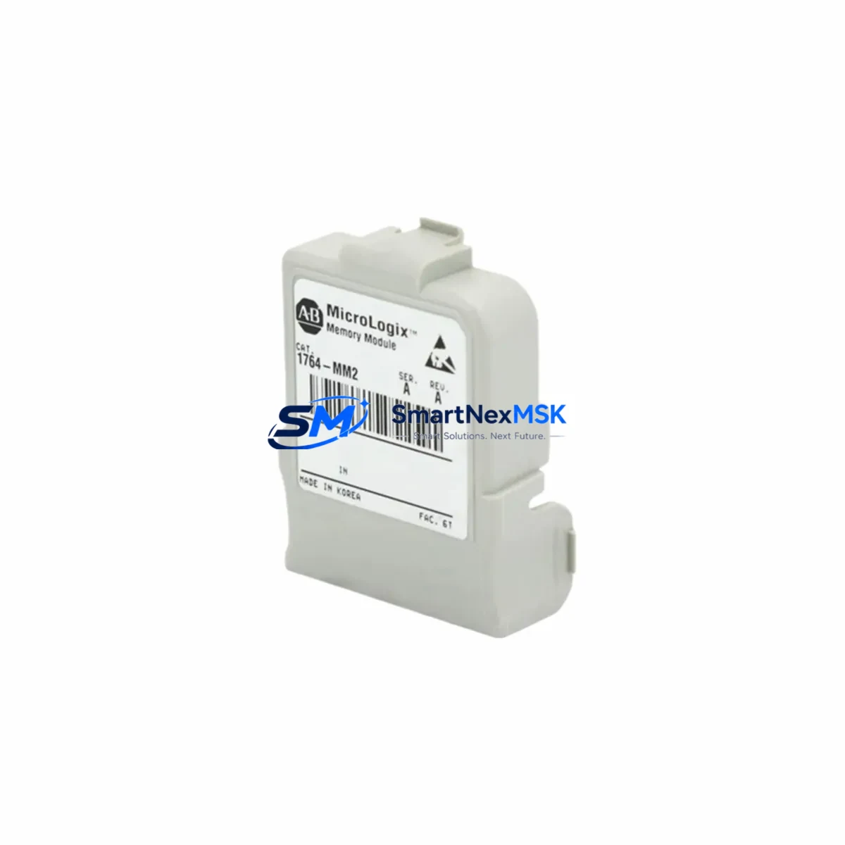
Allen-Bradley 1764-MM2 Spare for MicroLogix 1500 Automation
The Allen-Bradley 1764-MM2 is a 32K word memory expansion module designed exclusively for the MicroLogix 1500 programmable controller platform. In industrial maintenance environments where unplanned downtime translates directly into production loss, having a verified, original-specification 1764-MM2 spare on the shelf is a fundamental risk-control measure. SMARTNEXMSK supplies this module as a maintenance-ready spare — pre-tested, properly packaged, and backed by a 12-month warranty — so your maintenance and procurement teams can act decisively when a memory fault or controller replacement event occurs.
The MicroLogix 1500 controller family, including the 1764-LRP and 1764-LSP processor units, relies on the 1764-MM2 to extend onboard program and data memory for applications with larger ladder logic programs, extensive data table requirements, or complex recipe management routines. When a controller exhibits memory-related faults — such as fault code S:6 memory errors, corrupted program files, or failure to retain configuration after power cycling — the 1764-MM2 is a primary diagnostic and replacement target. Maintenance engineers should treat this module as a consumable spare in any facility running MicroLogix 1500-based control panels.
From a procurement standpoint, the 1764-MM2 is a legacy catalog item. Rockwell Automation has progressively reduced availability through standard distribution channels, making third-party industrial spare suppliers like SMARTNEXMSK a critical sourcing partner for facilities committed to extending the operational life of existing MicroLogix 1500 installations rather than undertaking full controller migrations.
Spare Maintenance Table
| Parameter | Specification |
|---|---|
| Part Number | 1764-MM2 |
| Brand | Allen-Bradley (Rockwell Automation) |
| Compatible Controller | MicroLogix 1500 (1764-LRP, 1764-LSP) |
| Memory Capacity | 32K Words (Program + Data) |
| Module Type | Plug-in Memory Expansion Module |
| Interface | Direct slot-mount to MicroLogix 1500 base unit |
| Operating Temperature | 0°C to 60°C (32°F to 140°F) |
| Storage Temperature | -40°C to 85°C |
| Humidity | 5% to 95% non-condensing |
| Power Supply | Powered via controller backplane (no external supply required) |
| Origin | United States |
| Application Environment | Industrial control panels, manufacturing automation, process control |
| Compatibility Verification | Confirmed for MicroLogix 1500 Series A and B |
| Warranty | 12 Months — covers manufacturing defects and functional failure under normal operating conditions |
| Condition | Original spare, tested prior to shipment |
Maintenance Planning for Continuous Operation
When a MicroLogix 1500 controller requires a 1764-MM2 replacement, experienced maintenance engineers know that the memory module is rarely the only component that warrants inspection. A thorough site assessment during the replacement window significantly reduces the risk of repeat failures and secondary faults.
Begin with the 1764-24BWA or 1764-28BXB base unit itself — inspect the module slot contacts for oxidation or mechanical damage before seating the new 1764-MM2. Simultaneously, verify the condition of the 1764-LRP processor module: check firmware revision, confirm the battery (1769-BA) is within service life, and back up the existing program via RSLogix 500 before any hardware swap.
The 24VDC control power supply feeding the MicroLogix 1500 panel should be load-tested during the maintenance window. Voltage sags or ripple on the DC bus are a common root cause of memory corruption events and intermittent controller faults. If the panel uses a 1606-XLP or 1606-XLS series power supply, verify output voltage under full I/O load and inspect capacitor condition if the unit has been in service for more than five years.
I/O modules installed in the same panel — particularly 1762-IQ8 digital input modules and 1762-OW8 relay output modules — should be inspected for contact wear, terminal torque, and wiring insulation condition. Relay output modules in high-cycle applications are a frequent maintenance item alongside memory and processor components.
For panels with communications requirements, inspect the 1761-NET-AIC Advanced Interface Converter or any 1747-KFC15 ControlNet interface in use. Communication module faults can masquerade as controller memory issues in diagnostic logs. Similarly, if the system uses 1769-SDN DeviceNet Scanner modules in an expanded rack, verify scanner configuration integrity after any processor or memory replacement.
Terminal blocks and wiring within the control cabinet — particularly Phoenix Contact or Weidmüller screw-clamp terminal strips — should be re-torqued and inspected for thermal discoloration, which may indicate intermittent overload conditions contributing to controller stress. Signal isolators on analog I/O circuits, such as MTL or Pepperl+Fuchs loop-powered isolators, should be verified for correct output range and calibration if the system handles process measurement signals.
Finally, if an HMI is connected to the MicroLogix 1500 — such as a 2711P-T7C22D9P PanelView Plus 7 or a legacy 2711-T10C8 PanelView 1000 — confirm that the communication driver and tag database remain intact after the controller memory replacement. HMI communication loss following a controller swap is a common post-maintenance issue that can be avoided with a pre-swap configuration export.
Site Replacement Workflow
Step 1 — Pre-Replacement Backup: Connect to the MicroLogix 1500 via RSLogix 500 and perform a full program upload to a secure engineering workstation. Document the current memory utilization report (Program File size, Data File allocation) to confirm the 1764-MM2 capacity is appropriate for the installed application.
Step 2 — Controller Power-Down: Follow site LOTO (Lockout/Tagout) procedures. Remove the 24VDC control power supply feed to the MicroLogix 1500 base unit. Allow 30 seconds for internal capacitors to discharge before opening the enclosure.
Step 3 — Module Removal: Locate the 1764-MM2 slot on the MicroLogix 1500 base unit (typically the rightmost expansion slot). Press the module release tab and extract the existing module. Inspect the slot connector for debris or pin damage.
Step 4 — New Module Installation: Align the replacement 1764-MM2 with the slot guide rails and press firmly until the retention latch engages. Do not force — correct alignment requires minimal insertion force.
Step 5 — Power-Up and Verification: Restore control power. The MicroLogix 1500 will perform a self-test. Using RSLogix 500, download the backed-up program to the controller. Verify memory utilization, confirm all I/O modules are recognized, and perform a controlled test cycle before returning the system to production.
Step 6 — Documentation: Record the replacement date, module serial number, and post-replacement test results in the site maintenance log. Update the spare parts inventory to trigger reorder of a replacement 1764-MM2 for the next maintenance event.
Spare Parts Support FAQ
Q1: Is the 1764-MM2 supplied by SMARTNEXMSK an original Allen-Bradley component?
Yes. SMARTNEXMSK sources 1764-MM2 modules from verified industrial supply channels. Each unit is inspected and function-tested prior to shipment. The 12-month warranty covers manufacturing defects and functional failure under normal operating conditions. Counterfeit or remanufactured modules are not supplied.
Q2: What is the recommended spare parts inventory strategy for MicroLogix 1500 installations?
For facilities with three or more MicroLogix 1500 controllers, maintaining a minimum of one 1764-MM2 and one 1764-LRP processor as cold spares is standard practice. Given the legacy status of the MicroLogix 1500 platform, procurement teams should consider securing a multi-unit buffer stock to hedge against future supply constraints. SMARTNEXMSK supports blanket order arrangements for volume spare parts programs.
Q3: How is compatibility with my specific MicroLogix 1500 configuration verified before shipment?
The 1764-MM2 is compatible with all MicroLogix 1500 base units (1764-24BWA, 1764-28BXB) and both processor types (1764-LRP, 1764-LSP) across Series A and B hardware revisions. If your installation uses a non-standard firmware revision or a modified base configuration, provide your controller catalog number and series letter when placing your order and our technical team will confirm compatibility before dispatch.
Q4: What does the 12-month warranty cover and how is a warranty claim processed?
The 12-month warranty covers functional failure attributable to manufacturing defects under normal industrial operating conditions (per the environmental specifications in the table above). It does not cover damage from incorrect installation, overvoltage events, or physical mishandling. To initiate a warranty claim, contact SMARTNEXMSK with the order reference number and a description of the observed fault. Replacement units are dispatched upon fault verification, with return shipping of the defective module arranged by our logistics team.
© 2026 SMARTNEXMSK. All rights reserved.
Original Source: https://smartnexmsk.com
Contact: [email protected] | +86 18259474341



