
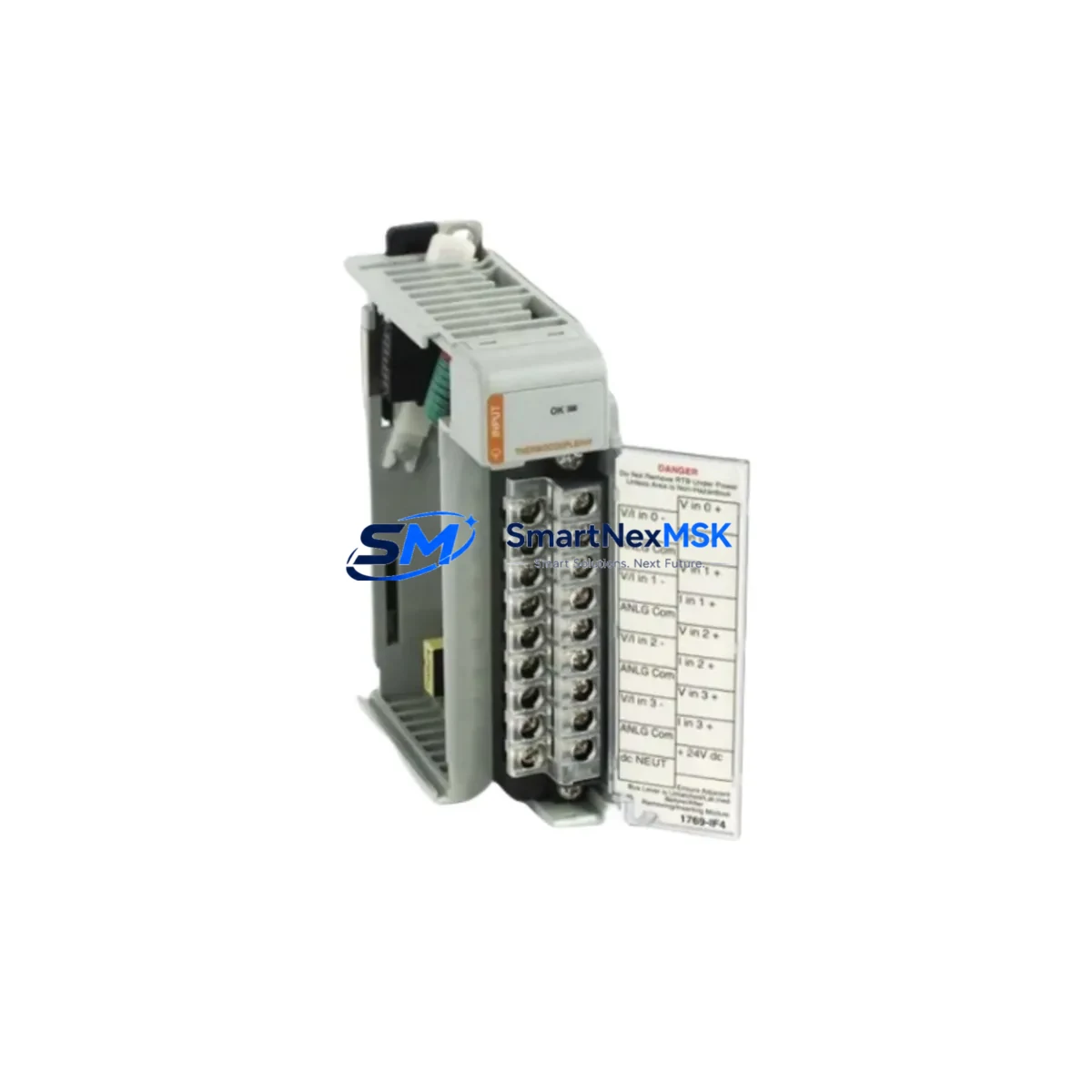
Allen-Bradley 1769-IT6 Maintenance-Ready Spare for 1769 Automation
The Allen-Bradley 1769-IT6 is a 6-channel thermocouple and millivolt input module designed for the CompactLogix 1769 series control platform. In industrial maintenance environments — from automotive assembly lines to food processing facilities and water treatment plants — this module is a critical front-line component for temperature monitoring and process control. When a 1769-IT6 fails or degrades, the result is immediate: loss of thermocouple signal integrity, erroneous PLC readings, and potential unplanned shutdown of the entire control loop. Holding a verified original spare on the shelf is the single most effective strategy for minimizing mean time to repair (MTTR) and protecting production continuity.
This listing provides an original, tested Allen-Bradley 1769-IT6 module sourced for maintenance and emergency replacement use. Each unit undergoes pre-shipment functional verification and ships with a 12-month warranty covering manufacturing defects and operational failure under normal industrial conditions.
Spare Maintenance Table
| Parameter | Specification |
|---|---|
| Part Number / SKU | 1769-IT6 |
| Brand | Allen-Bradley (Rockwell Automation) |
| Series | CompactLogix 1769 |
| Module Type | Thermocouple / Millivolt Analog Input |
| Input Channels | 6 (individually configurable) |
| Thermocouple Types Supported | J, K, E, T, R, S, B, N, C |
| mV Input Range | ±100 mV |
| Resolution | 16-bit |
| Backplane Current Draw | 75 mA @ 5 VDC |
| Operating Temperature | 0 °C to 60 °C |
| Storage Temperature | -40 °C to 85 °C |
| Relative Humidity | 5% to 95% non-condensing |
| Compatibility | CompactLogix 1769-L16ER, 1769-L18ER, 1769-L24ER, 1769-L27ERM, 1769-L30ER, 1769-L33ER, 1769-L36ERM and compatible 1769 bus systems |
| Installation | Right-end or left-end of 1769 bus; DIN rail or panel mount |
| Cold Junction Compensation | Automatic, internal |
| Open-Wire Detection | Yes, per channel |
| Certifications | UL, CE, C-Tick |
| Country of Origin | United States |
| Warranty | 12 Months — covers manufacturing defects and operational failure |
| Pre-Shipment Testing | Functional verification performed on every unit |
Maintenance Planning for Continuous Operation
When a maintenance or reliability engineer schedules a planned inspection or responds to a thermocouple fault alarm on a CompactLogix system, replacing the 1769-IT6 is rarely the only action required. A thorough site replacement procedure should include inspection of the entire signal chain and associated control cabinet components to prevent repeat failures and ensure system integrity.
Begin by verifying the 1769-PA2 or 1769-PB2 power supply module — an aging or undersized power supply is a common root cause of intermittent analog input errors that are misdiagnosed as module failure. Check output voltage stability under load before installing the replacement 1769-IT6. Next, inspect the 1769-IQ16 or 1769-IQ32 digital input modules in the same chassis for signs of backplane communication errors, which can cascade and affect analog module diagnostics.
Thermocouple wiring integrity is equally critical. Inspect all thermocouple extension cables and compensating cables for insulation damage, moisture ingress, and correct polarity. A single reversed thermocouple pair will produce inverted temperature readings that are difficult to diagnose without signal tracing. Verify terminal block torque values on the 1769-IT6 field wiring connector and replace any corroded or loose terminals.
For systems using mixed analog I/O, also inspect the 1769-IF4 or 1769-IF8 analog input modules sharing the same 1769 bus. Crosstalk or ground loop issues between analog channels can affect thermocouple measurement accuracy. A signal isolator or signal conditioner installed upstream of the 1769-IT6 inputs is recommended in high-noise environments such as motor control centers or variable frequency drive (VFD) cabinets.
Communication health should be confirmed via the 1769-L-series CompactLogix processor — check the I/O tree in Studio 5000 Logix Designer for any inhibited or faulted module slots. If the system uses EtherNet/IP communication via a 1769-AENTR adapter, verify adapter firmware version compatibility with the replacement module. For legacy systems still running DeviceNet via a 1769-SDN scanner module, confirm node addressing has not been disrupted during the replacement procedure.
Finally, review the 1769-ECR or 1769-ECL end cap condition — a cracked or improperly seated end cap can cause intermittent backplane faults that mimic module failure. Keeping a spare end cap alongside the 1769-IT6 in your critical spares kit is a low-cost, high-value practice.
Site Replacement Workflow
Step 1 — Pre-replacement verification: Before removing the faulted module, document the channel configuration in Studio 5000 Logix Designer (thermocouple type per channel, filter frequency, open-wire fault action, and engineering unit scaling). Export the program backup to a USB drive or network share.
Step 2 — Safe isolation: Place the CompactLogix processor in Program mode via the keyswitch or software. Confirm all outputs controlled by thermocouple-dependent logic are in a safe state. De-energize the field wiring connector before disconnecting thermocouple leads.
Step 3 — Module swap: Remove the faulted 1769-IT6 by releasing the top and bottom bus levers. Insert the replacement module and confirm the bus levers lock fully. Reconnect the field wiring connector, verifying polarity and terminal torque (0.5–0.6 N·m recommended).
Step 4 — Configuration restore: The 1769-IT6 stores no onboard configuration — all channel parameters reside in the controller project. Return the processor to Run mode and verify all six channels report valid temperature readings within expected process range. Check the module’s diagnostic bits in the I/O image table for any open-wire or over-range faults.
Step 5 — Post-replacement documentation: Record the replacement date, module serial number, and channel verification results in the site maintenance log. Update the spare parts inventory to trigger reorder of a replacement 1769-IT6 for the critical spares shelf.
This workflow is compatible with all 1769 CompactLogix bus configurations and supports hot-swap replacement on systems with redundant power architectures. The replacement 1769-IT6 is a direct form-fit-function substitute for the original — no firmware update or hardware modification is required.
Spare Parts Support FAQ
Q1: Is this 1769-IT6 a genuine original Allen-Bradley module or a compatible substitute?
This is an original Allen-Bradley 1769-IT6 module. It is not a third-party compatible or clone. Each unit is sourced from authorized supply channels and undergoes functional pre-shipment testing to confirm channel accuracy, backplane communication, and open-wire detection performance.
Q2: What is the recommended spare parts inventory strategy for the 1769-IT6?
For facilities operating more than two CompactLogix systems with thermocouple I/O, maintaining a minimum of one 1769-IT6 per control cabinet is recommended. For critical process lines where thermocouple failure triggers a full line shutdown, a 2:1 spare ratio (two spares per installed module) is industry best practice. The 12-month warranty period supports a rolling stock rotation strategy.
Q3: How is compatibility with my specific CompactLogix processor confirmed before shipment?
The 1769-IT6 is compatible with all 1769-series CompactLogix processors and 1769 bus expansion systems. Compatibility is confirmed by verifying the target system uses a standard 1769 backplane bus. If your system uses a non-standard or legacy bus configuration, provide your processor model number (e.g., 1769-L30ER) and we will confirm compatibility before shipment.
Q4: What does the 12-month warranty cover and how is a warranty claim processed?
The 12-month warranty covers manufacturing defects, backplane communication failure, channel measurement error beyond published specification, and open-wire detection malfunction under normal industrial operating conditions. Warranty claims are processed by contacting [email protected] with the order number, module serial number, and a description of the fault. Replacement units are dispatched within 3 business days of claim verification.
© 2026 SMARTNEXMSK. All rights reserved.
Original Source: https://smartnexmsk.com
Contact: [email protected] | +86 18259474341



