
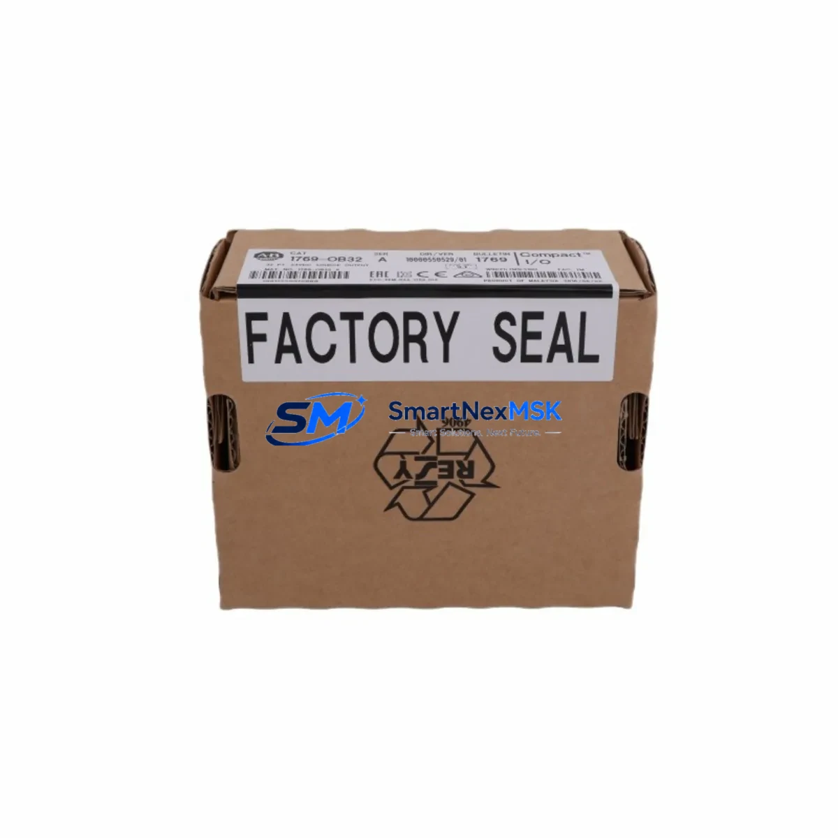
Allen-Bradley 1769-OB32T Spare for Compact I/O Automation: Maintenance-Ready Replacement for Uninterrupted Industrial Operations
The Allen-Bradley 1769-OB32T is a 32-point sourcing transistor output module designed for the 1769 Compact I/O platform, widely deployed in discrete manufacturing, packaging lines, material handling systems, and process automation cells. When this module fails or degrades, the downstream impact is immediate: conveyor drives lose command signals, solenoid valves freeze in position, and safety interlocks may trigger unplanned shutdowns. Holding a verified original spare on the shelf is the single most effective strategy for minimizing mean time to repair (MTTR) and protecting production continuity.
At SMARTNEXMSK, every 1769-OB32T unit is sourced from authorized supply chains, inspected against factory electrical specifications, and tested under load prior to shipment. Each module ships with a 12-month warranty covering manufacturing defects and functional failures, giving maintenance engineers and procurement teams the confidence to stock this part as a long-term asset rather than a one-time emergency purchase.
Spare Maintenance Table
| Parameter | Specification |
|---|---|
| Part Number / SKU | 1769-OB32T |
| Brand / Manufacturer | Allen-Bradley (Rockwell Automation) |
| Series / Platform | 1769 Compact I/O |
| Module Type | 32-Point Sourcing Transistor Output |
| Output Voltage Range | 10–28.8 VDC |
| Output Current per Point | 0.5 A (max) |
| Total Module Current | 4 A (max, all outputs ON) |
| Output Protection | Electronic short-circuit and overload protection |
| Backplane Current Draw (5 VDC) | 185 mA |
| Backplane Current Draw (24 VDC) | 0 mA |
| Operating Temperature | 0 °C to 60 °C (32 °F to 140 °F) |
| Storage Temperature | -40 °C to 85 °C |
| Relative Humidity | 5–95% non-condensing |
| Compatibility | MicroLogix 1500, CompactLogix L-series, 1769 bus adapters |
| Mounting | DIN rail or panel mount via 1769 bus connector |
| Certifications | UL, CE, cUL |
| Country of Origin | United States |
| Warranty | 12 Months — covers manufacturing defects and functional failures |
| Condition | Original spare — new or factory-refurbished, tested before shipment |
| Shipping | Global express; ESD-safe packaging; traceable logistics |
Maintenance Planning for Continuous Operation
Replacing a 1769-OB32T in the field is rarely an isolated task. Experienced maintenance engineers know that an output module failure is often a symptom of broader stress in the control cabinet. Before returning the system to service, a structured inspection of adjacent components is essential to prevent repeat failures and ensure the replacement module operates within its rated parameters.
Power supply integrity is the first checkpoint. The 1769-PA2 or 1769-PB2 power supply modules feeding the Compact I/O bus should be verified for stable 5 VDC and 24 VDC rails. A sagging or noisy supply is a leading cause of premature output module failure. If the power supply is more than five years old or shows signs of capacitor aging, plan its replacement alongside the 1769-OB32T.
Bus connector and backplane health must be confirmed. The 1769 bus connector linking adjacent modules can develop micro-cracks or oxidized contacts after years of thermal cycling. Inspect the connector on both the failed module and its neighbors. A damaged bus connector will cause the replacement 1769-OB32T to fault immediately on power-up, leading to misdiagnosis.
Field wiring and terminal blocks deserve close attention. The 1769-OB32T drives 32 output points, each connected through field-side terminal wiring. Check for loose terminations, insulation breakdown, or corroded conductors — particularly on points that switch high-cycle loads such as solenoid valves or motor starters. Terminal blocks showing discoloration or heat damage should be replaced before reconnecting the new module.
Input-side verification is equally important. If the output module failure was triggered by a field fault (short circuit, overload), the corresponding input signals from sensors or limit switches — often routed through a companion 1769-IQ32 or 1769-IQ16 input module — should be tested to confirm the fault condition has been cleared. Replacing the output module without resolving the field fault will damage the new unit.
Communication and processor health should be assessed at the same time. The CompactLogix or MicroLogix 1500 processor communicating with the 1769-OB32T may log diagnostic fault codes that reveal whether the failure was electrical, thermal, or firmware-related. Review the controller’s fault log and confirm the 1769-L3x or 1769-L2x processor firmware is current. If a 1761-NET-ENI or 1769-SDN DeviceNet scanner is present in the rack, verify its status LEDs and communication health as well.
Relay output modules and signal isolation in the same cabinet should be inspected during the same maintenance window. If the control cabinet includes a 1769-OW8 relay output module driving higher-voltage loads, check relay contact wear and coil resistance. Signal isolators protecting analog I/O channels from ground loops should also be tested — a failed isolator can inject noise that causes erratic output behavior even after the digital output module is replaced.
Fusing and overcurrent protection on the output field side must be verified. Each output group on the 1769-OB32T is protected electronically, but field-side fuses or circuit breakers protecting the 24 VDC load supply should be inspected and replaced if they show signs of thermal stress. Maintaining a stock of appropriate fuse ratings alongside the output module spare is a best practice for rapid recovery.
Proactive spare parts planning for a 1769 Compact I/O system should include the 1769-OB32T alongside companion modules such as the 1769-IQ32 digital input module, 1769-OF4 analog output module, 1769-IF4 analog input module, and the 1769-ECR end cap resistor. These components share the same bus architecture and failure modes, making them natural candidates for a consolidated spare parts kit.
Site Replacement Workflow
Step 1 — Isolate and de-energize. Follow your site’s lockout/tagout (LOTO) procedure. De-energize the 24 VDC field supply to the output module before disconnecting any wiring. Do not rely solely on the controller’s output disable command — physically isolate the field power.
Step 2 — Document the existing configuration. Before removing the failed 1769-OB32T, photograph the wiring connections and record the module’s slot position in the I/O rack. If the controller is online, export the I/O configuration from Studio 5000 Logix Designer or RSLogix 500 to confirm the module’s configured parameters (output data size, fault mode, program mode state).
Step 3 — Remove the failed module. Disconnect the field wiring terminal block (the 1769-OB32T uses a removable terminal block, which simplifies replacement without rewiring). Slide the module off the bus connector by releasing the top and bottom locking tabs. Inspect the bus connector pins on the adjacent module for damage before installing the replacement.
Step 4 — Install the replacement 1769-OB32T. Slide the new module onto the bus connector until it clicks into place. Reconnect the removable terminal block. The module’s configuration is stored in the controller, so no manual parameter entry is required — the processor will automatically recognize the replacement module upon power-up if the catalog number matches.
Step 5 — Power up and verify. Restore field power and bring the controller online. Confirm the module’s status LED shows solid green (module OK, communication established). Force individual output points in the controller to verify field device response. Clear any latched faults in the controller fault log before returning the system to automatic mode.
Step 6 — Update maintenance records. Log the replacement date, module serial number, and any associated field repairs. Update your spare parts inventory to trigger reorder of the consumed 1769-OB32T unit, maintaining minimum stock levels for future incidents.
This workflow applies equally when upgrading from an older 1769-OB32 (non-T variant) to the 1769-OB32T. The T-suffix variant offers improved electronic protection and is a direct drop-in replacement in most 1769 rack configurations, reducing downtime risk during legacy system life extension projects.
Spare Parts Support FAQ
Q1: Is the 1769-OB32T compatible with both MicroLogix 1500 and CompactLogix systems?
Yes. The 1769-OB32T is fully compatible with any controller that supports the 1769 Compact I/O bus, including MicroLogix 1500 (via 1769-L35E or similar) and CompactLogix L-series processors (1769-L30ER, 1769-L33ER, etc.). Compatibility is determined by the bus adapter and controller firmware version. Always verify your controller’s I/O compatibility list in the Rockwell Automation product compatibility and download center before installation.
Q2: What is included in the 12-month warranty, and how is a warranty claim processed?
The 12-month warranty covers manufacturing defects, functional failures under normal operating conditions, and DOA (dead on arrival) units. It does not cover damage caused by incorrect installation, overvoltage events, or physical mishandling. To initiate a warranty claim, contact SMARTNEXMSK at [email protected] with your order number, a description of the failure, and photographic evidence. Replacement units are dispatched within 3–5 business days upon claim approval.
Q3: How do you verify the module is genuine and tested before shipment?
Every 1769-OB32T unit sourced by SMARTNEXMSK undergoes incoming inspection against factory electrical specifications, including output voltage compliance, current capacity per point, and backplane communication handshake testing. Units are shipped in ESD-safe packaging with a test report available upon request. Traceability documentation (lot number, inspection date) is retained for 24 months post-shipment.
Q4: What is the recommended minimum stock quantity for a production facility running multiple 1769 Compact I/O racks?
For facilities operating 3 or more 1769 Compact I/O racks in critical production roles, SMARTNEXMSK recommends maintaining a minimum of 2 units of the 1769-OB32T on-site. For facilities with 24/7 continuous operations or long lead-time procurement environments, a buffer of 3–4 units is advisable. Pairing this with at least one spare 1769-IQ32 input module and one 1769-PA2 power supply covers the majority of unplanned downtime scenarios in a 1769-based control system.
© 2026 SMARTNEXMSK. All rights reserved.
Original Source: https://smartnexmsk.com
Contact: [email protected] | +86 18259474341



