
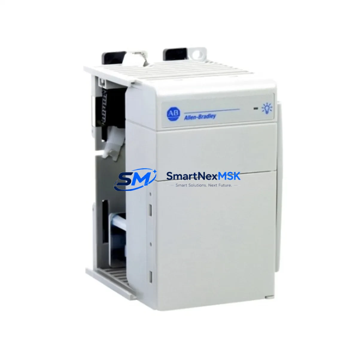
Allen-Bradley 1769-PA2 Retrofit-Ready AC Power Supply for CompactLogix Control Systems
The Allen-Bradley 1769-PA2 is a 120/240V AC input power supply module designed for the CompactLogix 1769 series control platform. As legacy automation systems age and original spare parts become increasingly difficult to source, the 1769-PA2 serves as a critical retrofit and replacement component for engineers managing aging control cabinets, upgrading discontinued hardware, or restoring production lines after unexpected failures. SMARTNEXMSK maintains verified stock of the 1769-PA2, fully tested and backed by a 12-month warranty, ready for immediate shipment to minimize your downtime.
Upgrade Compatibility Table
| Parameter | Details |
|---|---|
| Compatible Platform | Allen-Bradley CompactLogix 1769 Series |
| Input Voltage | 85–265V AC, 47–63 Hz |
| Output Power | 30W (1769 bus) |
| Backplane Interface | 1769 right-end bus connector |
| Mounting | DIN rail or panel mount, standard 1769 form factor |
| Communication Compatibility | Compatible with EtherNet/IP, DeviceNet, and ControlNet topologies via associated 1769-L3x controllers |
| Common Replacement Targets | 1769-PA2 (same SKU restock), 1769-PB2 (DC variant cross-reference) |
| Retrofit Recommendation | Direct drop-in for existing 1769 backplane; verify total bus current draw before installation |
| Commissioning Notes | Confirm module address assignment in RSLogix 5000 / Studio 5000; validate I/O tree after power-up |
| Warranty | 12 Months — covers manufacturing defects and functional failure under normal operating conditions |
Retrofit Planning for Existing Automation Systems
When planning a retrofit around the 1769-PA2, the power supply is rarely the only component under review. In most CompactLogix-based control cabinets, the power supply works in concert with a 1769-L30ER or 1769-L33ER controller module, which manages the program logic and EtherNet/IP communications. Engineers replacing the 1769-PA2 should simultaneously audit the 1769-ECR end cap and 1769-CRR3 right-to-right bus connector to ensure the backplane assembly remains mechanically and electrically sound.
For systems that include analog or digital I/O expansion, modules such as the 1769-IF4 analog input module or the 1769-OB16 digital output module must be verified for bus current compatibility against the 1769-PA2’s 30W output rating. Exceeding the rated bus load is a common cause of intermittent faults during retrofit commissioning. A full I/O current audit — summing the draw of each installed module — should be completed before the new power supply is energized.
In control cabinets that also house a PanelView Plus 7 HMI terminal communicating over EtherNet/IP, the HMI screen layouts and tag bindings should be validated after the controller is restored. Tag address changes or program slot reassignments during the retrofit can cause HMI communication faults that appear unrelated to the power supply replacement but are triggered by the system restart sequence.
For older installations that include a 1769-SDN DeviceNet scanner module or a 1769-ASCII serial communication module, protocol migration planning is essential. If the retrofit is part of a broader upgrade from DeviceNet to EtherNet/IP, the 1769-PA2 power supply installation is typically the first step, followed by scanner module replacement and network reconfiguration. Programming cables such as the 1784-U2DHP USB-to-DH+ adapter may be required to access legacy controller configurations during the transition.
All units supplied by SMARTNEXMSK are functionally tested prior to shipment. Each 1769-PA2 is verified for output voltage stability, inrush current behavior, and bus connector integrity. Units are shipped with original-specification packaging and include a 12-month warranty covering manufacturing defects and operational failure under standard industrial conditions.
Downtime Control During System Migration
Minimizing production downtime during a CompactLogix power supply replacement requires preparation before the maintenance window begins. The most effective approach is to export and archive the current controller program from Studio 5000 or RSLogix 5000 before any hardware is disturbed. This ensures that if the controller loses its program during the power cycle — which can occur if the battery-backed memory module (1769-BAT) is depleted — the logic can be reloaded immediately without delay.
Prior to de-energizing the panel, document the terminal wiring on the 1769-PA2’s AC input terminals (L1, L2/N, and ground) with photographs or a wiring diagram. The 1769-PA2 uses a standard screw-terminal block that can be removed as a unit, preserving wire labeling and reducing reconnection time. After the new module is seated on the backplane and the bus connector is engaged, restore power and observe the module status indicators: the green PWR LED should illuminate steadily, and the controller’s RUN LED should follow within the normal boot sequence.
If the system includes remote I/O racks connected via 1769-ARM address reserve modules or expansion cables, verify that each remote rack re-establishes communication before releasing the line back to production. A structured commissioning checklist — covering power-up sequence, I/O status verification, HMI reconnection, and a short production trial run — is the most reliable method for confirming that the retrofit has been completed successfully and that control continuity has been maintained.
Retrofit Support FAQ
Q: Is the 1769-PA2 a direct replacement for an existing unit of the same part number?
A: Yes. The 1769-PA2 is a same-SKU replacement and installs directly into the existing 1769 backplane position without mechanical or electrical modification. Verify that the total bus current draw of all installed I/O and communication modules does not exceed the 30W output rating before powering up.
Q: What wiring changes are required when replacing the 1769-PA2?
A: The AC input terminal block on the 1769-PA2 is removable. In most cases, the existing terminal block can be transferred directly to the replacement module, eliminating the need to re-terminate individual wires. Confirm wire gauge and torque specifications match the module’s terminal ratings before energizing.
Q: How do I verify compatibility with my existing CompactLogix controller and I/O configuration?
A: Open your Studio 5000 or RSLogix 5000 project and review the I/O tree for the 1769 local chassis. Sum the bus current requirements listed in the module properties for each installed module. If the total is within the 1769-PA2’s 30W / 2A bus output, the replacement is compatible. For systems with a 1769-L3x controller and multiple I/O modules, this check is critical.
Q: What does the 12-month warranty cover, and how is it handled?
A: The 12-month warranty covers manufacturing defects and functional failure under normal industrial operating conditions. If a unit fails within the warranty period, SMARTNEXMSK will arrange a replacement shipment after fault verification. Contact [email protected] with your order reference and a description of the fault to initiate a warranty claim.
© 2026 SMARTNEXMSK. All rights reserved.
Original Source: https://smartnexmsk.com
Contact: [email protected] | +86 18259474341



