
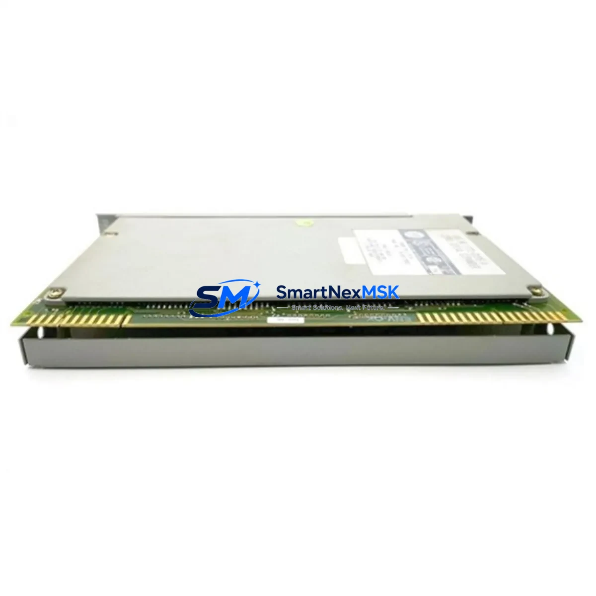
Allen-Bradley 1771-DXPS Maintenance-Ready Spare for PLC-5 Automation
The Allen-Bradley 1771-DXPS is a Control Coprocessor module designed for the PLC-5 programmable controller platform — one of the most widely deployed legacy automation architectures in discrete manufacturing, process control, and material handling industries. For maintenance engineers managing aging PLC-5 control cabinets, the 1771-DXPS represents a critical spare: its failure directly impacts coprocessor-assisted ladder logic execution, coordinated motion sequencing, and inter-rack communication integrity. Sourcing a verified, tested replacement unit is the fastest path to restoring full system operation and minimizing unplanned downtime.
At SMARTNEXMSK, every 1771-DXPS unit undergoes pre-shipment functional verification, covering power-on self-test, backplane communication handshake, and I/O channel integrity checks. Units are supplied with a 12-month warranty and are ready for immediate installation into 1771-series I/O chassis. Whether you are executing a planned maintenance rotation, responding to an emergency fault, or building a strategic spare parts buffer for a multi-line PLC-5 facility, this module ships with full traceability documentation.
Spare Maintenance Table
| SKU / Part Number | 1771-DXPS |
| Brand | Allen-Bradley (Rockwell Automation) |
| Series | PLC-5 / 1771 I/O Platform |
| Module Type | Control Coprocessor |
| Compatible Chassis | 1771-A1B, 1771-A2B, 1771-A3B, 1771-A4B series I/O chassis |
| Backplane Interface | 1771 parallel I/O backplane |
| Power Requirement | Supplied via 1771 chassis backplane (5 VDC logic bus) |
| Operating Temperature | 0°C to 60°C (32°F to 140°F) |
| Relative Humidity | 5% to 95% non-condensing |
| Origin | USA |
| Weight | 900 g (approx.) |
| Compatibility | PLC-5/10, PLC-5/15, PLC-5/20, PLC-5/25, PLC-5/30, PLC-5/40, PLC-5/60, PLC-5/80 |
| Maintenance Recommendation | Inspect backplane connector pins, verify chassis slot assignment, confirm firmware revision compatibility before installation |
| Pre-Shipment Test | Power-on self-test, backplane handshake, I/O channel verification |
| Warranty | 12 Months — covers manufacturing defects and functional failure under normal operating conditions |
Maintenance Planning for Continuous Operation
When a 1771-DXPS coprocessor fault is detected — whether through a PLC-5 fault code, an unexpected program halt, or a failed rack diagnostic — the replacement workflow should extend beyond the module itself. Experienced maintenance engineers treat a coprocessor failure as a trigger for a broader cabinet inspection, because associated components are often stressed by the same root cause: power transients, thermal cycling, or connector oxidation.
Begin with the 1771-P4S or 1771-P7 chassis power supply: verify output voltage rails are within specification, as an under-voltage condition on the 5 VDC backplane bus is a common contributor to coprocessor faults. Next, inspect the 1771-ASB remote I/O adapter if the rack is configured as a remote chassis — a degraded ASB module can cause intermittent coprocessor communication errors that mimic hardware failure. Check all 1771-IB or 1771-OB discrete I/O modules in the same chassis for bent backplane connector pins or cracked housings, as physical damage during module removal is a frequent secondary issue.
For systems using coordinated motion or high-speed counting, inspect the 1771-IXHR encoder/counter input module and any associated 1771-OFE analog output modules — these are often part of the same control loop as the coprocessor and should be verified for correct calibration after a coprocessor swap. If the PLC-5 processor communicates over Data Highway Plus (DH+), test the 1784-KTX or 1784-PKTX communication interface card in the programming terminal to confirm the network is stable post-replacement.
Terminal blocks and wiring within the control cabinet should also be inspected: 1492-series terminal blocks and associated wiring ferrules are common points of intermittent contact failure in high-vibration environments. Finally, if the facility uses PanelView 550 or PanelView 600 HMI terminals connected to the PLC-5 via DH+ or RS-232, verify that the HMI communication parameters are intact after the coprocessor replacement, as some firmware versions require a communication re-initialization sequence.
Building a structured spare parts kit around the 1771-DXPS — including at minimum one spare chassis power supply, one ASB adapter, and a set of the most-used I/O modules — is the most effective strategy for reducing mean time to repair (MTTR) in PLC-5-based production lines.
Site Replacement Workflow
Step 1 — Pre-Replacement Documentation: Before removing the faulty 1771-DXPS, photograph the module’s slot position, record the chassis address switch settings, and note the firmware revision label on the module faceplate. This documentation is essential if the replacement unit requires configuration matching.
Step 2 — Safe De-energization: Follow your facility’s lockout/tagout (LOTO) procedure. Remove power from the 1771 chassis via the upstream disconnect. Do not rely solely on the chassis power switch — verify zero-energy state with a calibrated meter on the backplane power terminals.
Step 3 — Module Removal: Release the module locking tab, pull the 1771-DXPS straight out of the backplane slot, and place it in an ESD-protective bag immediately. Inspect the vacated slot’s backplane connector for bent pins or debris before inserting the replacement.
Step 4 — Replacement Installation: Verify the replacement 1771-DXPS address switches match the original configuration. Seat the module firmly into the chassis slot until the locking tab engages. Restore power and observe the module’s status indicators during the power-on self-test sequence.
Step 5 — System Verification: From the RSLogix 5 programming terminal, perform a full I/O force test on the affected rack. Confirm that all coprocessor-dependent rungs execute correctly and that no new fault codes are present in the PLC-5 fault table. Document the replacement in your CMMS with the new module’s serial number and installation date.
This workflow is compatible with direct replacement of legacy 1771-DXPS units without requiring PLC-5 program modification, preserving system compatibility and eliminating the need for costly re-engineering or re-commissioning.
Spare Parts Support FAQ
Q1: Is the 1771-DXPS still available as a new or refurbished spare, and what is its supply outlook?
The 1771-DXPS has been discontinued by Rockwell Automation as part of the broader PLC-5 platform end-of-life. However, verified surplus and refurbished units remain available through specialist industrial spare parts suppliers. SMARTNEXMSK maintains stock of tested 1771-DXPS modules and can advise on long-term supply strategy, including recommended buffer stock quantities based on your installed base size and criticality classification.
Q2: How is compatibility verified before shipment?
Each 1771-DXPS unit is tested for backplane communication integrity and power-on self-test completion prior to shipment. Compatibility is confirmed against the 1771 I/O chassis family (A1B through A4B) and PLC-5 processor variants. If your application requires a specific firmware revision or hardware revision suffix, please provide this information at the time of inquiry so we can match accordingly.
Q3: What does the 12-month warranty cover, and how is a warranty claim processed?
The 12-month warranty covers functional failure and manufacturing defects under normal operating conditions — defined as installation within a 1771-series chassis operating within published environmental specifications. Warranty claims are initiated by contacting [email protected] with the order reference, fault description, and installation date. A replacement unit or credit is issued after fault verification, with typical turnaround of 3–5 business days.
Q4: Can the 1771-DXPS be used as a direct drop-in replacement without program changes?
Yes. The 1771-DXPS is a slot-compatible replacement for existing coprocessor installations within the PLC-5 / 1771 platform. No PLC-5 program modification is required provided the replacement unit’s address switch configuration matches the original. For systems with customized coprocessor firmware, consult your original system documentation or contact our technical support team to confirm revision compatibility before installation.
—
© 2026 SMARTNEXMSK. All rights reserved.
Original Source: https://smartnexmsk.com
Contact: [email protected] | +86 18259474341



