
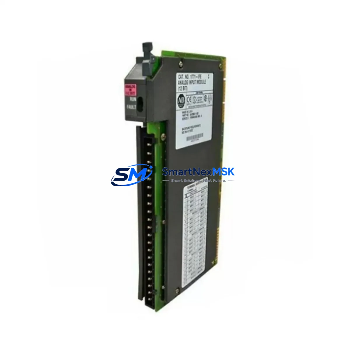
Allen-Bradley 1771-IFEK Spare for PLC-5 Automation: Spare Replacement & Industrial Downtime Risk Control
The Allen-Bradley 1771-IFEK is an 8-channel differential analog input module designed for the PLC-5 programmable controller platform — one of Rockwell Automation’s most widely deployed legacy control architectures in process manufacturing, utilities, and heavy industry. As original equipment reaches end-of-life and OEM support windows close, maintaining a verified spare of the 1771-IFEK is a critical element of any proactive maintenance strategy. This listing offers an original, tested, and warehouse-stocked 1771-IFEK spare module, ready for immediate dispatch with a 12-month warranty and full pre-shipment functional verification.
For maintenance engineers managing aging PLC-5 racks, the 1771-IFEK handles differential analog signal acquisition from field instruments including thermocouples, RTDs, pressure transmitters, and flow sensors. Signal integrity at the input stage is foundational — a degraded or failed 1771-IFEK can cause erratic process readings, false alarms, or complete loss of analog feedback loops, triggering unplanned shutdowns. Keeping a certified spare on the shelf eliminates the lead-time risk that turns a two-hour swap into a two-week procurement crisis.
Spare Maintenance Table
| Parameter | Specification / Detail |
|---|---|
| Part Number / SKU | 1771-IFEK |
| Brand | Allen-Bradley (Rockwell Automation) |
| Series | PLC-5 |
| Module Type | 8-Channel Differential Analog Input |
| Input Signal Range | ±10 V DC / 4–20 mA (configurable per channel) |
| Resolution | 12-bit (1 in 4096) |
| Backplane Compatibility | 1771 I/O Chassis (all standard rack sizes) |
| Power Consumption | 800 mA @ 5 V DC (backplane) |
| Operating Temperature | 0°C to 60°C (32°F to 140°F) |
| Isolation | Channel-to-backplane optical isolation |
| Installation | Direct slot insertion into 1771 I/O chassis; no tools required |
| Application Environment | Process control, utilities, oil & gas, water treatment, manufacturing |
| Condition | Original spare; pre-shipment functional test performed |
| Warranty | 12 Months from date of shipment |
| Origin | USA |
| Shipping | Global express; ESD-safe packaging |
Maintenance Planning for Continuous Operation
When a 1771-IFEK fails or shows signs of drift, the root cause is rarely isolated to the module alone. A thorough site inspection should accompany any analog input module replacement. Maintenance engineers should begin by verifying the 1771-PS13 or 1771-P4S power supply output — insufficient or noisy backplane power is a leading cause of premature analog module failure and erratic readings. Confirm that the 1771 I/O chassis backplane connectors are clean and free of oxidation before seating the replacement module.
Field wiring integrity is equally critical. Inspect terminal blocks and field wiring for loose connections, moisture ingress, or shielding breaks that could introduce common-mode noise into differential input channels. If the system uses signal isolators between field instruments and the 1771-IFEK — a common practice in high-noise environments — verify that the isolators are within calibration and functioning correctly, as a failed isolator can mimic a failed input module.
For PLC-5 systems with mixed I/O, also inspect adjacent modules in the same chassis. The 1771-OFE analog output module, 1771-IFE single-ended analog input module, and 1771-IX thermocouple/millivolt input module share the same backplane power budget and should be checked for proper seating and status indicators. If the PLC-5 processor — such as the 5/20, 5/30, 5/40, or 5/80 — is logging I/O faults, retrieve the fault table before clearing it; this data is invaluable for root-cause analysis.
Communication health should also be reviewed. If the PLC-5 is networked via Data Highway Plus (DH+) or Remote I/O (RIO) links, inspect the 1785-KA5 or 1771-ASB remote I/O adapter for fault indicators. A communication fault can mask or compound analog I/O issues. For systems with HMI integration, verify that the PanelView or FactoryTalk View terminal is receiving updated analog values after module replacement — a stale display can create false confidence in a system that is still faulted.
Finally, review the fuse and circuit protection for the analog input field loop power supply. A blown fuse on the 24 V DC field power rail will disable all transmitters connected to the 1771-IFEK channels simultaneously, producing a symptom pattern that closely resembles a failed module. Confirming field power continuity before condemning the module saves time and avoids unnecessary replacements.
Site Replacement Workflow
Step 1 — Pre-replacement documentation: Record all current analog input values and channel configurations from the PLC-5 processor data table before powering down. Photograph the existing module’s DIP switch settings — the 1771-IFEK uses onboard switches to configure input range and filter settings per channel group. These settings must be replicated exactly on the replacement module.
Step 2 — Safe power-down: Place the PLC-5 processor in Program mode and inhibit the affected I/O rack if the system supports partial rack inhibit. De-energize the 1771 chassis power supply. For live systems where a full shutdown is not possible, coordinate with the control room to place affected loops in manual mode at the DCS or SCADA level before proceeding.
Step 3 — Module extraction and inspection: Remove the failed 1771-IFEK and inspect the chassis slot connector for bent pins or debris. Clean with dry compressed air if necessary. Do not use solvents on backplane connectors.
Step 4 — Replacement module preparation: Configure the replacement 1771-IFEK DIP switches to match the documented settings. Verify the module firmware revision if the PLC-5 processor revision requires a specific module revision for compatibility — consult the 1771-IFEK installation manual (publication 1771-6.5.108).
Step 5 — Installation and verification: Seat the replacement module firmly into the chassis slot. Restore power and return the processor to Run mode. Monitor the I/O status indicators and verify that all eight analog input channels are reading correctly in the processor data table. Compare live readings against the pre-replacement baseline to confirm signal integrity.
Step 6 — Loop calibration check: For critical process loops, perform a loop calibration check using a calibrated signal source (e.g., 4 mA and 20 mA injection) to verify end-to-end accuracy before returning the system to automatic control.
Spare Parts Support FAQ
Q: Is this 1771-IFEK an original Allen-Bradley module or a third-party replacement?
A: This is an original Allen-Bradley 1771-IFEK module sourced from authorized industrial surplus channels. All units undergo pre-shipment functional testing to verify analog input performance across all eight channels before dispatch. No third-party or counterfeit substitutes are offered.
Q: What is the recommended spare parts inventory strategy for PLC-5 analog input modules?
A: For facilities with multiple PLC-5 racks, we recommend maintaining a minimum of one 1771-IFEK spare per four installed modules, with higher ratios for critical process applications. Given that Rockwell Automation has discontinued active production of PLC-5 I/O modules, sourcing verified spares now is strongly advisable to protect against future supply constraints and extended lead times.
Q: How is compatibility with my specific PLC-5 chassis and processor verified?
A: The 1771-IFEK is compatible with all standard 1771 I/O chassis sizes (4-slot through 16-slot) and all PLC-5 processor variants (5/11, 5/20, 5/30, 5/40, 5/60, 5/80). Compatibility is determined by chassis slot type (single-slot module) and backplane power availability. Please provide your chassis catalog number and processor series when ordering if you require additional compatibility confirmation.
Q: What does the 12-month warranty cover, and what is the return process?
A: The 12-month warranty covers functional failure under normal operating conditions from the date of shipment. If the module fails within the warranty period, we provide a replacement or full refund after fault verification. Contact our technical team with the module serial number and a description of the failure mode to initiate a warranty claim. Modules damaged by incorrect installation, overvoltage, or physical impact are not covered under warranty terms.
© 2026 SMARTNEXMSK. All rights reserved.
Original Source: https://smartnexmsk.com
Contact: [email protected] | +86 18259474341



