
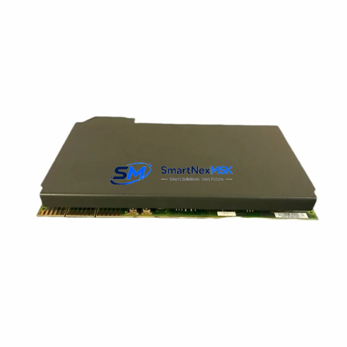
Allen-Bradley 1771-IFF/A Retrofit-Ready Analog Input for PLC-5 Control Systems
The Allen-Bradley 1771-IFF/A is an 8-channel, 12-bit analog input module designed for the PLC-5 processor family and the 1771 I/O chassis platform. As legacy PLC-5 systems approach end-of-life and original spare parts become increasingly scarce, the 1771-IFF/A remains one of the most sought-after retrofit components for engineers tasked with sustaining continuous process control without a full system overhaul. Whether you are replacing a failed module in a running production line, upgrading a control cabinet to extend its operational lifespan, or migrating analog signal acquisition to a more maintainable architecture, this module provides a verified, wiring-compatible solution backed by a 12-month warranty and pre-shipment functional testing.
Each 1771-IFF/A unit accepts standard 4–20 mA or 1–5 V analog input signals across all eight channels, converting them to 12-bit digital values for processing by the PLC-5 controller. The module occupies a single slot in the 1771 backplane and communicates directly with the processor via the 1771 I/O chassis backplane interface — no additional communication modules or protocol converters are required for direct replacement in existing installations. Terminal block wiring follows the original Rockwell Automation field wiring diagram, allowing technicians to reconnect field instruments without rewiring the marshalling panel.
Upgrade Compatibility Table
| Parameter | Detail |
|---|---|
| Module SKU | 1771-IFF/A |
| Compatible Platform | Allen-Bradley PLC-5 / 1771 I/O Chassis |
| Channels | 8 Analog Input Channels |
| Resolution | 12-bit (0–4095 counts) |
| Input Signal Range | 4–20 mA / 1–5 VDC |
| Backplane Interface | 1771 Single-Slot, Direct Backplane Communication |
| Terminal Block | Removable field wiring terminal block (original pinout retained) |
| Power Requirement | Supplied via 1771 chassis backplane (no external 24 VDC required) |
| Communication Compatibility | Native PLC-5 I/O scan; compatible with Data Highway Plus (DH+) networked systems |
| Replacement Recommendation | Direct drop-in for failed or end-of-life 1771-IFF/A units; verify chassis slot addressing before installation |
| Commissioning Notes | Confirm module address in RSLogix 5 I/O configuration; verify scaling in analog input rung logic |
| Warranty | 12-Month Warranty — Functional test report available on request |
Retrofit Planning for Existing Automation Systems
Successful integration of the 1771-IFF/A into an aging control system requires a structured pre-installation review. Begin by auditing the 1771 I/O chassis — confirm that the chassis backplane, typically a 1771-A1B, 1771-A2B, or 1771-A4B rack, has sufficient available slots and that the chassis power supply (such as the 1771-P4S or 1771-P7) can support the additional module load. Overloaded chassis power supplies are a common cause of intermittent analog read errors after module replacement and must be verified before the new module is seated.
Next, review the existing terminal block wiring. The 1771-IFF/A uses a removable terminal block that can be transferred directly from the failed module to the replacement unit, preserving field wiring continuity and eliminating the risk of miswiring during the swap. Confirm that each field instrument — flow transmitters, pressure transducers, temperature transmitters — is still within its calibrated range and that the 4–20 mA loop is intact before powering the new module.
In the RSLogix 5 programming environment, verify the I/O configuration file to confirm the module’s slot address and block transfer read (BTR) instruction parameters. If the original program uses Block Transfer instructions to read analog data from the 1771-IFF/A, confirm that the BTR length and control block address remain consistent with the replacement module’s data file mapping. Incorrect BTR configuration is the most frequent source of analog data errors following a module swap.
For systems that also incorporate a 1771-SDN DeviceNet Scanner or a 1771-ACN15 ControlNet Adapter in adjacent chassis slots, confirm that the I/O tree in RSLogix 5 reflects the correct module type at the replaced slot. Systems running on a Data Highway Plus (DH+) network with a 1785-KE or 1784-KTX communication card should not require network reconfiguration for a same-slot, same-type module replacement. However, if the chassis is connected to an HMI — such as a PanelView 550 or PanelView 900 running FactoryTalk View ME — verify that the analog tag addresses referenced in HMI screens remain valid after the swap. Tag address mismatches between the PLC data file and the HMI screen can cause display faults that are often mistaken for module failures.
For sites planning a broader migration from PLC-5 to ControlLogix, the 1771-IFF/A can serve as a bridge module during a phased cutover. Using a 1756-DHRIO bridge module in the ControlLogix chassis, the existing PLC-5 I/O chassis can remain online while the new 1756-L71 or 1756-L83E controller is commissioned in parallel. This approach allows engineers to validate the new control logic against live process data before cutting over, significantly reducing the risk of unplanned downtime during the migration.
Downtime Control During System Migration
Minimizing downtime during a 1771-IFF/A replacement or a broader PLC-5 system migration depends on preparation, not speed. The most effective strategy is to complete all pre-installation verification steps — chassis power audit, terminal block inspection, RSLogix 5 I/O configuration review, and HMI tag validation — before the maintenance window begins. A well-prepared technician can complete a single-module swap in under 30 minutes; an unprepared one can extend a planned 2-hour window into a multi-shift outage.
Where process conditions allow, perform a hot-swap simulation by placing the system in manual control mode at the DCS or SCADA level before removing the failed module. This preserves output states on connected actuators and prevents process upsets caused by analog input loss during the swap. For critical loops — such as reactor temperature control or compressor surge protection — coordinate with the process control team to confirm that the loop can be held in manual for the duration of the replacement.
After seating the replacement 1771-IFF/A, power up the chassis and observe the module status LED. A solid green LED confirms backplane communication is established. Force the BTR instruction in RSLogix 5 to execute a single read cycle and verify that analog values are within expected engineering unit ranges before returning the loop to automatic control. Document the as-found and as-left analog readings for each channel as part of the maintenance record. Ship the failed module for evaluation — our team provides a functional test report for all returned units under the 12-month warranty program.
Retrofit Support FAQ
Q: Is the 1771-IFF/A a direct drop-in replacement for my existing module?
A: Yes. The 1771-IFF/A is a same-SKU replacement that retains the original backplane slot footprint, terminal block pinout, and RSLogix 5 I/O configuration parameters. No program changes are required for a direct swap in the same chassis slot. Confirm the module address in the I/O configuration file before powering up.
Q: Has this module been tested before shipment?
A: Every 1771-IFF/A unit is functionally tested on a live 1771 chassis prior to shipment. A test report confirming channel-by-channel analog input verification is available on request. All units are covered by a 12-month warranty from the date of shipment.
Q: Can this module be used during a phased PLC-5 to ControlLogix migration?
A: Yes. The 1771-IFF/A can remain in service in the existing 1771 chassis while a ControlLogix system is commissioned in parallel using a 1756-DHRIO bridge. This allows a phased cutover with live process validation before the final switchover, protecting original program logic and minimizing migration risk.
Q: What wiring changes are needed when installing the replacement module?
A: None, if the original terminal block is intact. The removable terminal block from the failed module transfers directly to the replacement unit. If the terminal block is damaged, a replacement block with the original pinout is available. Verify field instrument loop integrity (4–20 mA continuity) before powering the new module.
© 2026 SMARTNEXMSK. All rights reserved.
Original Source: https://smartnexmsk.com
Contact: [email protected] | +86 18259474341



