
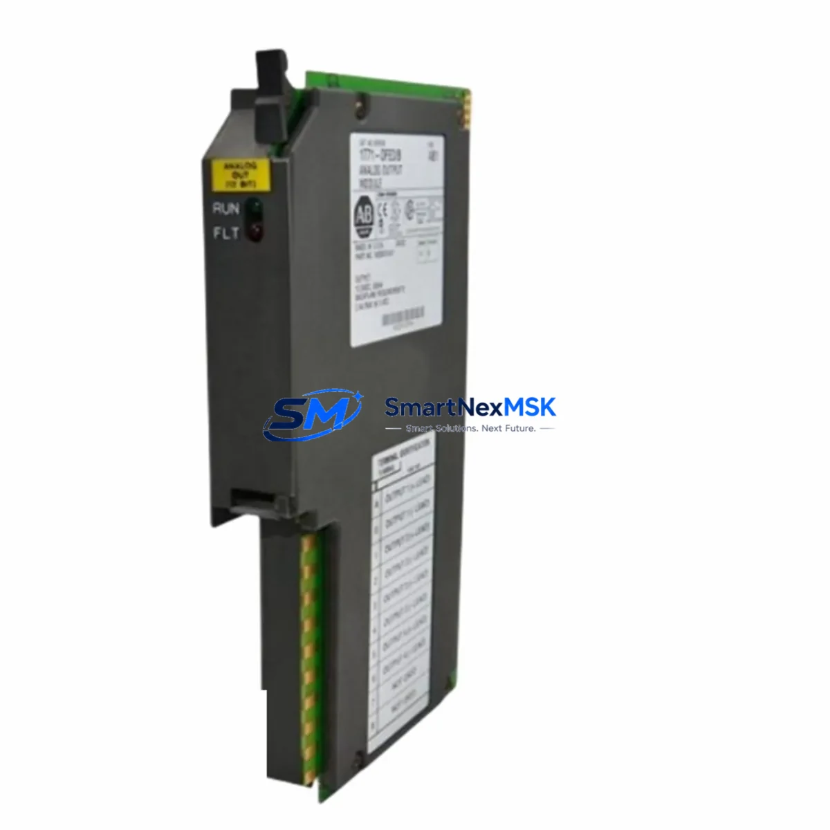
Allen-Bradley 1771-OFE3 Maintenance-Ready Spare PLC-5: Spare Replacement & Industrial Downtime Risk Control
The Allen-Bradley 1771-OFE3 is a 4-channel analog output module designed for the PLC-5 programmable controller platform and the 1771 I/O chassis system. In industrial automation environments where continuous process control is non-negotiable, maintaining a verified spare of the 1771-OFE3 on the shelf is a fundamental element of any credible maintenance strategy. Whether your facility operates batch processing lines, continuous flow systems, or discrete manufacturing cells, the analog output signals generated by this module — typically 4–20 mA current loops or 0–10 V voltage outputs — drive critical field devices including control valves, variable frequency drives, and positioners. A failed or degraded 1771-OFE3 can halt production within minutes, making rapid spare availability the single most effective downtime mitigation measure available to maintenance and procurement engineers.
This listing provides an original Allen-Bradley 1771-OFE3 sourced from authorized supply channels, fully tested prior to shipment, and backed by a 12-month warranty. Each unit undergoes functional verification of all four output channels before dispatch, ensuring the module is ready for immediate installation upon arrival at your facility.
Spare Maintenance Table
| Parameter | Specification |
|---|---|
| Part Number / SKU | 1771-OFE3 |
| Brand | Allen-Bradley (Rockwell Automation) |
| Series | PLC-5 / 1771 I/O |
| Module Type | Analog Output Module |
| Output Channels | 4 Channels |
| Output Signal Types | 4–20 mA (current) / 0–10 V (voltage), software-selectable per channel |
| Resolution | 12-bit (4096 steps) |
| Chassis Compatibility | 1771 I/O Chassis (all standard slot widths) |
| PLC Compatibility | PLC-5/10, PLC-5/15, PLC-5/20, PLC-5/30, PLC-5/40, PLC-5/60, PLC-5/80 |
| Power Consumption | Backplane-powered via 1771 chassis |
| Operating Temperature | 0°C to 60°C (32°F to 140°F) |
| Relative Humidity | 5% to 95% non-condensing |
| Installation | Single-slot 1771 I/O chassis module, keyed connector |
| Wiring | Field wiring via 1771-WN or compatible wiring arm |
| Isolation | Channel-to-backplane isolation provided |
| Condition | Original spare — new or fully refurbished to OEM specification |
| Pre-shipment Testing | All 4 output channels functionally verified |
| Warranty | 12 Months from date of shipment |
| Origin | USA |
| Lead Time | In-stock: ships within 1–3 business days |
Maintenance Planning for Continuous Operation
When a 1771-OFE3 analog output module fails or shows signs of drift, the replacement event is rarely isolated. Experienced maintenance engineers know that a module failure in a PLC-5 control cabinet often signals broader stress on adjacent components that share the same backplane power budget, field wiring harness, or process loop. A thorough site inspection during the replacement window should extend beyond the module itself.
Begin by inspecting the 1771 I/O chassis backplane for signs of corrosion, bent connector pins, or thermal discoloration — a degraded backplane can cause intermittent faults across multiple modules even after a new 1771-OFE3 is installed. Check the 1771-P4S or 1771-P7 power supply output voltage under load; an aging power supply delivering marginal voltage is a common root cause of analog module instability and should be replaced proactively if it is beyond its service life.
Review the field wiring arm — typically a 1771-WN wiring arm — for terminal corrosion, loose screw connections, or insulation breakdown on signal cables. In 4–20 mA current loop circuits, high-resistance connections introduce offset errors that can be misdiagnosed as module failure. While the cabinet is open, inspect any signal isolators or loop-powered signal conditioners in the analog output circuits; these components protect the module from field-side transients and should be tested for proper isolation resistance.
If the PLC-5 processor — such as a 1785-L40B or 1785-L60B processor module — has not been inspected recently, verify its battery status and check for any active fault codes related to I/O communication. A processor with a failing memory backup battery may lose configuration data during a power cycle, compounding the downtime caused by the original module fault.
For systems using 1771-SDN DeviceNet Scanner or 1771-KE RS-232 communication modules in the same chassis, confirm that the replacement of the 1771-OFE3 does not shift slot addressing in a way that disrupts the I/O map. Slot-keying and I/O configuration files in the PLC-5 program must be verified after any module swap.
Where the analog outputs drive variable frequency drives or servo amplifiers, coordinate with the electrical team to verify that the output signal scaling and engineering unit conversion in the PLC-5 program matches the input range expected by the field device. A correctly installed 1771-OFE3 paired with an incorrectly scaled PLC program will produce process deviations that can be difficult to diagnose without oscilloscope verification at the field terminal.
Finally, if your facility maintains a 1771-IFE or 1771-IFE16 analog input module in the same chassis for closed-loop feedback, inspect it during the same maintenance window. Analog input and output modules in the same control loop age together and often exhibit correlated degradation patterns. Replacing both during a planned outage is more cost-effective than scheduling a second emergency shutdown weeks later.
Site Replacement Workflow
Step 1 — Preparation and isolation: Before removing the 1771-OFE3, place the PLC-5 processor in Program mode and confirm that all field devices driven by the four analog output channels are in a safe state (valves closed, drives at zero speed, or held by independent safety interlocks). Document the current output values from the PLC program for post-replacement verification.
Step 2 — Module removal: De-energize the 1771 chassis or confirm that hot-swap is supported in your specific chassis revision. Disconnect the 1771-WN wiring arm from the module — do not disconnect individual field wires from the arm terminals. Remove the module from the chassis slot, noting the slot number and keying configuration.
Step 3 — Replacement module preparation: Verify that the replacement 1771-OFE3 carries the same catalog suffix and firmware revision as the removed unit. Check the module’s output type jumper or DIP switch configuration (current vs. voltage output per channel) and match it to the removed module’s configuration before installation. This step eliminates the most common cause of post-replacement process deviations.
Step 4 — Installation and wiring reconnection: Insert the replacement module into the correct chassis slot, ensuring the keying tab engages properly. Reconnect the 1771-WN wiring arm. Restore chassis power and return the processor to Run mode.
Step 5 — Functional verification: Force each of the four output channels through their full engineering unit range from the PLC program and verify the corresponding field device response. Confirm that 4–20 mA loop currents are within ±0.1 mA of commanded values using a calibrated loop calibrator. Log the verification results in the maintenance record.
Step 6 — Documentation and spare replenishment: Update the equipment maintenance log with the replacement date, module serial number, and verification results. Immediately initiate a purchase order for a replacement spare to restore your on-hand inventory to the minimum stocking level. Downtime risk is highest in the period between a spare being consumed and its replacement arriving.
Spare Parts Support FAQ
Q1: Is this 1771-OFE3 compatible with all PLC-5 processor variants?
Yes. The 1771-OFE3 is compatible with all standard PLC-5 processor families — including the PLC-5/10, /15, /20, /30, /40, /60, and /80 — when installed in a standard 1771 I/O chassis. Compatibility is determined by the chassis backplane and I/O configuration file in the PLC-5 program, not by the specific processor model. Always verify the I/O map and slot assignment in your PLC program before installation.
Q2: What pre-shipment testing is performed on each unit?
Every 1771-OFE3 shipped from our inventory undergoes functional output verification on all four channels in both current (4–20 mA) and voltage (0–10 V) output modes. Modules that fail any channel test are quarantined and not shipped. A test record is available upon request. All units are shipped with ESD-protective packaging to prevent transit damage.
Q3: How should I manage long-term spare inventory for legacy PLC-5 systems?
For PLC-5 systems that are no longer in active production by Rockwell Automation, we recommend maintaining a minimum of two 1771-OFE3 spares per chassis in your on-site inventory, with at least one additional unit held at your regional warehouse or with a trusted distributor. Given the age profile of most PLC-5 installations, lead times for emergency procurement can be unpredictable. A proactive stocking strategy — reviewed annually as part of your spare parts lifecycle audit — is the most reliable way to protect against extended unplanned downtime.
Q4: What does the 12-month warranty cover, and what is the claims process?
The 12-month warranty covers functional failure of the module under normal operating conditions — correct supply voltage, within-specification operating temperature, and proper installation per the 1771-OFE3 user manual. Physical damage caused by incorrect installation, overvoltage events, or field wiring faults is not covered. To initiate a warranty claim, contact our technical support team with the order number, module serial number, and a description of the fault symptom. We will arrange return shipping and provide a replacement or full refund within 10 business days of receiving the returned unit.
© 2026 SMARTNEXMSK. All rights reserved.
Original Source: https://smartnexmsk.com
Contact: [email protected] | +86 18259474341



