
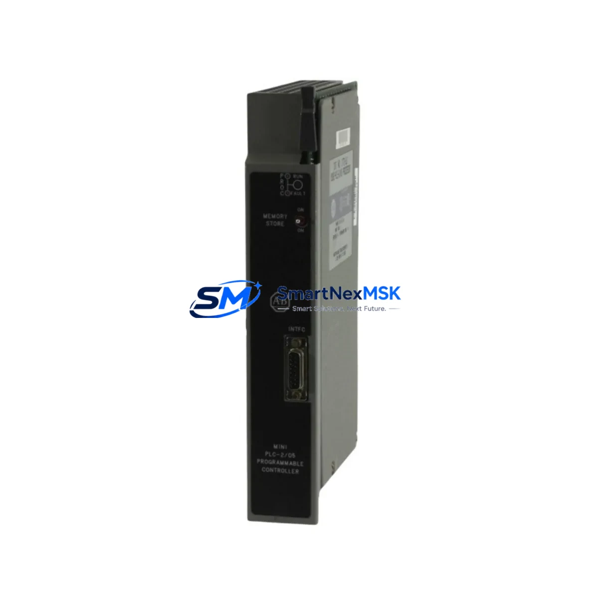
Allen-Bradley 1772-LS Retrofit-Ready Processor for PLC-2 Control Systems
The Allen-Bradley 1772-LS is a legacy mini-PLC processor module originally designed for the PLC-2 family of programmable logic controllers. As production lines built around the PLC-2/05 and PLC-2/30 platforms approach end-of-life, the 1772-LS remains one of the most sought-after retrofit components for facilities that need to maintain operational continuity without committing to a full platform migration. SMARTNEXMSK maintains verified stock of the 1772-LS to support planned upgrades, emergency replacements, and phased modernization projects across manufacturing, utilities, and process control environments.
Whether your facility is replacing a failed processor, upgrading a control cabinet, or migrating from a discontinued PLC-2 architecture to a more supportable platform, the 1772-LS serves as the critical bridge component. Its compatibility with the original 1771 I/O chassis and backplane architecture means that existing terminal wiring, I/O modules, and field device connections can often be preserved during the transition, significantly reducing retrofit labor costs and downtime exposure.
Before installing a replacement 1772-LS, engineers should verify the following: power supply capacity on the 1771 chassis (typically the 1771-P4 or 1771-P7 power supply), backplane slot addressing and module keying, processor memory size and program storage compatibility, communication port configuration (DH-485 or RS-232 via the 1772-SD2 programming cable), and whether the existing ladder logic program stored on EEPROM or external media is compatible with the replacement unit’s firmware revision. Skipping any of these verification steps is a common cause of post-replacement faults and extended commissioning time.
For facilities running HMI panels such as the PanelView 550 or PanelView 600 connected via DH-485, it is essential to confirm that the communication driver and tag database remain intact after processor swap. In many legacy installations, the HMI screen logic references specific data table addresses (N7, B3, F8 registers) that must be preserved in the replacement processor’s program file. Failure to validate this mapping before go-live is a leading cause of unplanned downtime during retrofit commissioning.
Upgrade Compatibility Table
| Parameter | Detail |
|---|---|
| Replaces / Compatible With | Allen-Bradley 1772-LS, 1772-LSP, 1772-LX, PLC-2/05, PLC-2/30 |
| Chassis Compatibility | 1771 I/O Chassis (4, 8, 12, 16 slot) |
| Power Supply Requirement | 1771-P4 / 1771-P7 (verify capacity before installation) |
| Communication Ports | DH-485, RS-232 (programming via 1772-SD2 cable) |
| Programming Software | APS (6200 Series), AI Series; verify firmware revision match |
| I/O Module Compatibility | 1771 series discrete and analog I/O modules |
| Backplane Interface | 1771 parallel backplane; confirm slot keying and addressing |
| HMI Compatibility | PanelView 550/600 via DH-485; validate data table address mapping |
| Retrofit Recommendation | Preserve original wiring; verify EEPROM program before swap |
| Commissioning Focus | Module address, program file integrity, communication link test |
| Warranty | 12-Month Warranty — functional test report available on request |
Retrofit Planning for Existing Automation Systems
A successful 1772-LS retrofit begins well before the replacement unit arrives on-site. The first step is a full audit of the existing control cabinet: document the 1771 chassis slot layout, record the I/O module types and addresses (including any 1771-OBD discrete output modules, 1771-IFE analog input modules, or 1771-OFE analog output modules), and photograph all terminal wiring before disconnection. This documentation becomes the baseline for post-retrofit verification.
Next, back up the existing PLC-2 program using the 1772-SD2 programming cable connected to a PC running APS or AI Series software. Store the program file in at least two locations. If the original processor is still partially functional, perform a full online upload before removal. If the processor has failed completely, check whether a backup program file exists on EEPROM cartridge or in the facility’s maintenance records — many sites running legacy PLC-2 systems have not updated their program backups in years, which creates significant risk during unplanned replacements.
During the physical swap, pay close attention to the 1771 chassis backplane connector and module keying strips. The 1772-LS uses a specific keying configuration that must match the chassis slot. After seating the replacement module, restore power incrementally: energize the 1771-P4 power supply first, confirm the processor status LEDs, then download the program file and perform a controlled I/O scan before enabling outputs. For systems with 1771-ASB remote I/O adapter modules connecting distributed I/O racks, verify that the remote I/O scanner configuration in the processor program matches the physical rack addresses.
Communication link verification is the final pre-startup step. If the control system includes a 1785-KA communication adapter for DH+ network integration, or a 1770-KF2 serial interface for host computer connectivity, confirm that these devices recognize the replacement processor and that the network node address is correctly configured. Systems using a 1747-SN ScanPort module for DeviceNet integration should also be tested for proper scanner-to-processor handshaking before full production restart.
Downtime Control During System Migration
Minimizing downtime during a 1772-LS replacement requires a structured pre-outage preparation protocol. At least 48 hours before the planned maintenance window, complete the program backup, prepare the replacement module, gather all required tools (including the 1772-SD2 cable, a laptop with APS software, and a multimeter for power supply verification), and brief the operations team on the expected outage duration and restart sequence.
During the outage window, follow a strict sequence: safe shutdown of controlled equipment, de-energization of the 1771 chassis, physical module swap, power restoration, program download, I/O verification scan, and controlled output enable. Each step should be logged with a timestamp. For critical processes, consider staging a 1771 chassis with a pre-loaded 1772-LS as a hot-standby unit that can be swapped in within minutes if the primary replacement encounters issues.
After restart, monitor the system for a minimum of 30 minutes before returning to full production. Pay particular attention to analog I/O scaling (verify that 1771-IFE and 1771-OFE modules are reading and writing correct engineering unit values), timer and counter accumulator values (which are lost on power cycle and must be re-initialized if the process requires them), and any fault codes reported by the processor’s status word. Document the completed retrofit in the facility’s maintenance management system and update the program backup with the verified post-retrofit file.
Retrofit Support FAQ
Q: Is the 1772-LS a direct drop-in replacement for the 1772-LSP?
A: The 1772-LS and 1772-LSP share the same chassis form factor and backplane interface, but differ in memory capacity and feature set. The 1772-LSP offers expanded data table memory. Before substituting one for the other, verify that the existing program file does not exceed the memory capacity of the replacement unit. SMARTNEXMSK can provide a pre-shipment functional test report confirming the module’s memory and I/O scan performance.
Q: Can I reuse my existing terminal wiring and I/O modules after replacing the processor?
A: In most cases, yes. The 1771 I/O chassis backplane and terminal wiring are independent of the processor module. As long as the I/O module types, slot addresses, and keying configurations remain unchanged, existing field wiring can be preserved. However, always verify power supply capacity after adding or changing modules, as the 1771-P4 and 1771-P7 have defined current budgets per chassis.
Q: What commissioning tests should be performed after installing the replacement 1772-LS?
A: At minimum: (1) verify processor status LEDs indicate normal run mode, (2) perform a full I/O force test on discrete inputs and outputs, (3) confirm analog I/O scaling on all 1771-IFE and 1771-OFE channels, (4) test DH-485 communication with any connected HMI or programming terminal, and (5) run the process through one complete cycle under manual supervision before returning to automatic mode. All units shipped by SMARTNEXMSK include a pre-shipment functional test report.
Q: What warranty coverage is provided, and what does it include?
A: All 1772-LS units supplied by SMARTNEXMSK are covered by a 12-month warranty from the date of shipment. The warranty covers functional failure under normal operating conditions and includes technical support for installation and commissioning questions. Units are tested prior to shipment and a test report is available on request. For warranty claims or technical support, contact [email protected] or call +86 18259474341.
© 2026 SMARTNEXMSK. All rights reserved.
Original Source: https://smartnexmsk.com
Contact: [email protected] | +86 18259474341



