
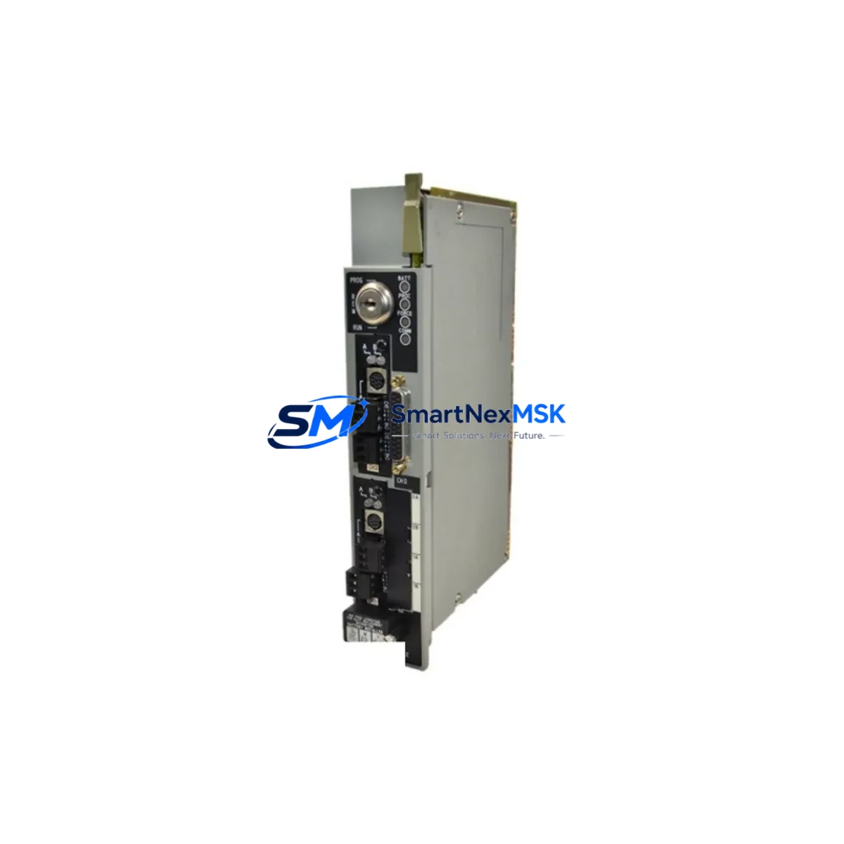
Allen-Bradley 1785-L40B Spare for PLC-5 Automation: Rapid Replacement & Downtime Risk Control
The Allen-Bradley 1785-L40B is the PLC-5/40 Enhanced Processor — a cornerstone controller in legacy Rockwell Automation architectures still operating across manufacturing, oil & gas, water treatment, and heavy industry facilities worldwide. When this processor fails or reaches end-of-service life, the impact is immediate: production lines halt, batch processes abort, and maintenance teams face intense pressure to restore control within the shortest possible window. Sourcing a verified, original-specification 1785-L40B spare is the single most effective action to compress that downtime window.
At SMARTNEXMSK, every 1785-L40B unit is sourced from controlled supply channels, subjected to pre-shipment functional verification, and dispatched with a 12-month warranty covering defects in materials and workmanship. Our inventory is maintained specifically to support maintenance engineers and procurement teams who cannot afford to wait weeks for a replacement processor.
Spare Maintenance Table
| Parameter | Specification / Detail |
|---|---|
| Part Number | 1785-L40B |
| Series / Model | PLC-5/40 Enhanced Processor |
| Brand | Allen-Bradley / Rockwell Automation |
| Memory | 48K Words (Data + Program) |
| I/O Capacity | Up to 3,072 discrete I/O points |
| Communication Ports | DH+ (Data Highway Plus), RS-232 (Channel 0) |
| Backplane Compatibility | 1771 I/O Chassis (PLC-5 family) |
| Power Supply Compatibility | 1771-P4S, 1771-P6S, 1771-P7 series |
| Operating Voltage | 5 VDC (supplied via backplane) |
| Operating Temperature | 0°C to 60°C (32°F to 140°F) |
| Relative Humidity | 5% to 95% non-condensing |
| Mounting | 1771 I/O Chassis slot (leftmost slot) |
| Programming Software | RSLogix 5 / 6200 Series |
| Compatibility | Drop-in replacement for 1785-L40B Series B/C/D |
| Condition | Original, pre-shipment tested |
| Warranty | 12 Months — defects in materials and workmanship |
| Lead Time | In-stock; ships within 1–3 business days |
| Origin | United States |
Maintenance Planning for Continuous Operation
Replacing the 1785-L40B processor is rarely an isolated task. Experienced maintenance engineers treat a processor swap as a trigger for a broader control cabinet inspection — because adjacent components in the same 1771 chassis and electrical circuit are subject to the same age, thermal stress, and power quality conditions that caused the original failure.
Before returning the system to service, verify the condition of the 1771-P4S or 1771-P6S power supply module that feeds the chassis. A degraded power supply is a leading cause of processor faults and memory corruption; replacing the processor without inspecting the supply risks a repeat failure within weeks. Similarly, inspect the 1771-ASB remote I/O adapter if the system uses distributed I/O racks — a marginal adapter can cause intermittent communication faults that are difficult to distinguish from processor issues.
Check all 1771-OAD and 1771-IAD discrete I/O modules in the chassis for signs of overheating, blown fuses, or failed output drivers. These modules share the backplane with the processor and can inject noise or voltage spikes that stress the CPU. For analog loops, inspect 1771-IFE or 1771-OFE analog I/O modules for calibration drift and verify signal integrity at the terminal base assemblies.
If the system communicates over a DH+ network, test the 1784-KTX or 1784-PKTX Data Highway Plus interface card in the programming workstation and inspect the DH+ trunk cable for impedance mismatches or damaged connectors. A faulty network interface can prevent successful program upload/download after the processor replacement, extending downtime unnecessarily.
For systems with an 1785-CHBM chassis backup module, verify that the backup program image is current before removing the failed processor. This ensures that if the replacement processor requires a fresh program load, a verified backup is immediately available. Also confirm that any 1771-SDN DeviceNet scanner module or 1785-L40C communication processor in the same rack is functioning correctly, as these modules interact directly with the main processor over the backplane.
Finally, inspect the control cabinet’s terminal blocks, fuse holders, and 24 VDC field power distribution. Loose terminations and blown fuses in the field wiring circuit are common secondary causes of I/O faults that persist after a processor replacement. A thorough cabinet inspection at the time of the processor swap prevents repeat service calls and supports a clean return-to-service sign-off.
Site Replacement Workflow
Step 1 — Pre-Replacement Backup: Using RSLogix 5 or a 6200-series programming terminal, upload and save the current ladder logic program, data table values, and processor configuration to a verified offline backup. Confirm the backup file integrity before proceeding.
Step 2 — Safe De-energization: Follow your site’s lockout/tagout (LOTO) procedure. Remove the 1771 chassis power supply key switch and verify zero energy state at the chassis backplane before handling the processor module.
Step 3 — Module Removal: Release the 1785-L40B from the leftmost chassis slot by pressing the top and bottom locking tabs simultaneously. Slide the module straight out along the backplane guides. Avoid touching the backplane connector pins.
Step 4 — Replacement Installation: Insert the new 1785-L40B into the same slot, ensuring the module seats fully against the backplane. Confirm the locking tabs engage. Verify that the processor series and firmware revision are compatible with your existing I/O configuration and communication settings.
Step 5 — Program Download and Verification: Re-energize the chassis and connect the programming terminal. Download the verified backup program. Confirm processor mode transitions correctly from PROGRAM to RUN. Verify all I/O status indicators and perform a functional test of critical outputs before releasing the system to production.
This workflow is designed to minimize mean time to repair (MTTR) and ensure system compatibility is maintained throughout the replacement process — preserving the integrity of the existing PLC-5 architecture without requiring hardware redesign or software migration.
Spare Parts Support FAQ
Q1: Is the 1785-L40B you supply an original Allen-Bradley unit, and how is it tested before shipment?
Yes. Every 1785-L40B we supply is an original Allen-Bradley / Rockwell Automation unit sourced from controlled channels. Prior to shipment, each unit undergoes functional verification including power-on self-test, memory integrity check, and communication port validation. A test report is available upon request. Units are shipped in anti-static packaging with physical inspection documentation.
Q2: What is the compatibility scope of the 1785-L40B, and can it replace earlier series variants?
The 1785-L40B is compatible with the full PLC-5/40 Enhanced Processor family and is a direct drop-in replacement for Series B, C, and D variants of the same part number. It operates in any standard 1771 I/O chassis and is fully compatible with RSLogix 5 programming software. For systems running older 6200-series software, firmware compatibility should be confirmed against your specific software version before installation.
Q3: What is your recommended spare parts stocking strategy for PLC-5/40 systems?
For facilities operating multiple PLC-5/40 systems, we recommend maintaining at least one 1785-L40B processor spare per production line or critical process loop. Given that the PLC-5 platform is in a mature lifecycle phase, lead times for new units from distribution channels can be unpredictable. Holding a verified spare on-site eliminates procurement lead time from your MTTR calculation entirely. We can support blanket order arrangements and consignment stocking programs for high-volume maintenance customers.
Q4: What does the 12-month warranty cover, and what is the return process if a unit is found defective?
The 12-month warranty covers defects in materials and workmanship under normal operating conditions. It does not cover damage resulting from incorrect installation, overvoltage events, or physical mishandling. If a unit is found defective within the warranty period, contact our support team at [email protected] with your order reference and a description of the fault. We will arrange return shipping and dispatch a replacement unit within 3 business days of receiving the defective module.
© 2026 SMARTNEXMSK. All rights reserved.
Original Source: https://smartnexmsk.com
Contact: [email protected] | +86 18259474341



