
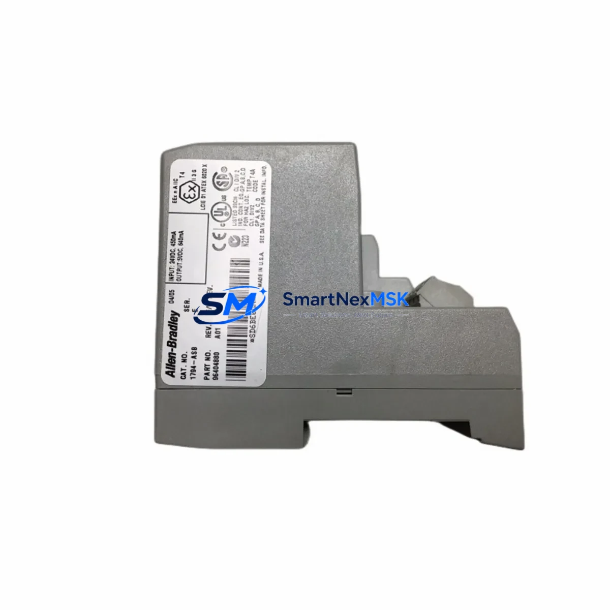
Allen-Bradley 1794-ASB Spare for Flex I/O Automation: Spare Replacement & Industrial Downtime Risk Control
The Allen-Bradley 1794-ASB is a Remote I/O Adapter module within the Rockwell Automation Flex I/O (1794 series) platform, designed for distributed control architectures where I/O nodes must communicate reliably over a Remote I/O network. In industrial environments — from automotive assembly lines to water treatment facilities — the 1794-ASB serves as the communication backbone between the PLC backplane and field-level I/O modules. When this adapter fails or degrades, the entire Flex I/O node goes offline, triggering unplanned downtime that can cost thousands of dollars per hour.
Sourcing a verified, original-specification 1794-ASB spare is the single most effective step a maintenance team can take to protect system availability. Our stock is sourced from authorized supply chains, individually tested prior to shipment, and backed by a 12-month warranty — giving procurement engineers the confidence to hold this part as a critical shelf spare without risk of obsolescence-driven failure.
Whether you are managing a planned turnaround, responding to an emergency fault, or building out a preventive maintenance (PM) kit for aging 1794-series nodes, the 1794-ASB should be a first-priority line item on your spare parts list.
Spare Maintenance Table
| Parameter | Specification / Detail |
|---|---|
| Part Number / SKU | 1794-ASB |
| Brand | Allen-Bradley (Rockwell Automation) |
| Series | Flex I/O — 1794 Series |
| Module Type | Remote I/O Adapter |
| Network Protocol | Remote I/O (RIO) |
| Backplane Compatibility | 1794 Flex I/O terminal bases (e.g., 1794-TB3, 1794-TB32) |
| Power Supply Voltage | 24V DC (field-side); backplane powered via terminal base |
| I/O Module Slots | Up to 8 Flex I/O modules per adapter node |
| Operating Temperature | 0°C to 55°C (32°F to 131°F) |
| Enclosure Rating | IP20 (panel-mount, control cabinet installation) |
| Origin | USA |
| Condition | Original, new or refurbished-to-spec; tested before shipment |
| Warranty | 12 Months |
| Lead Time | In stock — ships within 1–3 business days |
| Maintenance Recommendation | Inspect annually; replace at first sign of communication faults or LED error codes |
Maintenance Planning for Continuous Operation
When a 1794-ASB adapter is flagged for replacement during a scheduled inspection or emergency fault response, experienced maintenance engineers know that the adapter itself is rarely the only component that needs attention. A thorough site assessment should cover the entire Flex I/O node and its upstream control infrastructure.
Start with the 1794 terminal base (such as the 1794-TB3 or 1794-TB32): corrosion on the backplane connector or cracked housing can cause intermittent communication errors that mimic adapter faults. Next, inspect the 24V DC power supply feeding the field side of the node — voltage sag or ripple is a leading cause of premature adapter failure. A dedicated 1794-PS13 or equivalent Flex I/O power supply should be verified for output stability under full load.
Check all 1794-series I/O modules seated in the node — digital input modules (e.g., 1794-IB16), digital output modules (e.g., 1794-OB16), and analog modules (e.g., 1794-IE8) should be reseated and inspected for bent pins or contamination. Wiring at the terminal base screw connections should be torqued to spec and checked for loose strands that can cause ground faults.
On the network side, inspect the Remote I/O coaxial cable and BNC connectors running from the PLC chassis to the 1794-ASB. Damaged shielding or improper termination resistors are common causes of node communication loss. If the upstream PLC is a PLC-5 or SLC 500 series controller, verify the scanner module (e.g., 1771-ASB or 1747-SN) is correctly configured for the node address and baud rate matching the 1794-ASB settings.
For control cabinets running mixed architectures, also check any signal isolators or barriers on analog I/O loops connected to the Flex I/O node — degraded isolation can introduce noise that triggers false fault conditions on the adapter. Finally, review the fuse or circuit breaker protecting the 24V DC supply rail; a nuisance trip here will take down the entire node even if the 1794-ASB itself is healthy.
Keeping one 1794-ASB, one spare terminal base, and a matched set of the most-used I/O modules on the shelf reduces mean time to repair (MTTR) from hours to minutes — a measurable improvement in overall equipment effectiveness (OEE).
Site Replacement Workflow
Step 1 — Fault Isolation: Use the RSLogix or Studio 5000 diagnostic screen to confirm the fault is isolated to the 1794-ASB adapter node. Check the adapter’s status LEDs: a solid red FAULT LED with no RIO activity confirms adapter-level failure rather than a field wiring issue.
Step 2 — Safe De-energization: Isolate the 24V DC field power supply to the node. Do not remove the adapter while the backplane is energized — this can damage the terminal base connector and adjacent I/O modules.
Step 3 — Module Swap: Remove the 1794-ASB by releasing the DIN rail latch and sliding the module off the terminal base. Install the replacement 1794-ASB, ensuring the backplane connector seats fully. The module address switches (if applicable) must be set to match the original node address before power-up.
Step 4 — Verification: Re-energize the field power supply and observe the adapter LEDs. A solid green RUN LED and flashing green RIO LED confirm successful communication with the PLC scanner. Verify all I/O points in the control system HMI or SCADA display return to normal status.
Step 5 — Documentation: Log the replacement in your CMMS (Computerized Maintenance Management System) with the date, technician name, and new module serial number. Update your spare parts inventory to trigger a reorder for the consumed 1794-ASB unit.
This workflow is compatible with legacy PLC-5 and SLC 500 Remote I/O architectures and does not require any software changes when replacing a like-for-like 1794-ASB module — minimizing downtime and eliminating the risk of configuration errors during emergency repairs.
Spare Parts Support FAQ
Q1: Is this 1794-ASB compatible with both PLC-5 and SLC 500 Remote I/O networks?
Yes. The 1794-ASB is designed to operate on Rockwell Automation’s Remote I/O network and is compatible with PLC-5 and SLC 500 scanner modules. Verify the node address switch settings and baud rate configuration match your existing network parameters before installation.
Q2: What pre-shipment testing is performed on the 1794-ASB?
Each unit undergoes functional power-on testing and communication verification before dispatch. Units are inspected for physical integrity, connector condition, and correct LED behavior under simulated backplane load. A test report is available upon request for critical applications.
Q3: How should I manage 1794-ASB inventory for a multi-node Flex I/O installation?
For installations with 5 or more 1794-ASB nodes, we recommend holding a minimum of one spare adapter per 5 nodes, with a reorder trigger set at consumption of the first unit. Pairing the adapter spare with a matched 1794 terminal base and a set of your most-used I/O modules creates a complete node-replacement kit that supports sub-30-minute MTTR targets.
Q4: What does the 12-month warranty cover?
The 12-month warranty covers manufacturing defects and functional failure under normal operating conditions. It includes free replacement or repair of the defective unit. Warranty claims require the original order reference and a brief fault description. The warranty does not cover damage caused by incorrect installation, overvoltage, or physical mishandling on site.
© 2026 SMARTNEXMSK. All rights reserved.
Original Source: https://smartnexmsk.com
Contact: [email protected] | +86 18259474341



