
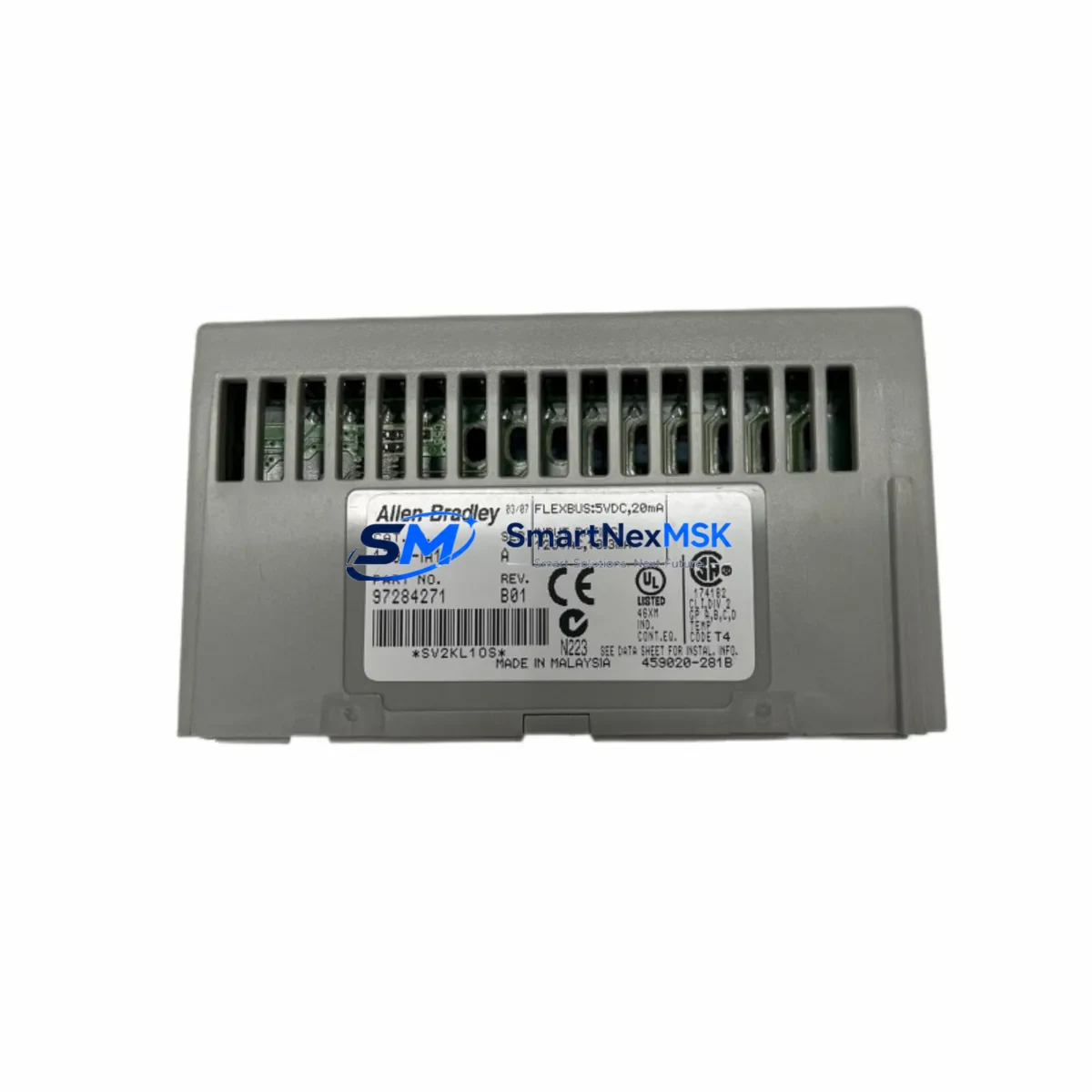
Allen-Bradley 1794-IRT8XT Retrofit-Ready TC/RTD Input for Flex XT Control Systems
When aging temperature measurement infrastructure begins to compromise process reliability, the Allen-Bradley 1794-IRT8XT delivers a proven, retrofit-ready solution for Flex XT distributed I/O systems. Designed as an 8-channel thermocouple and RTD input module, the 1794-IRT8XT supports a wide range of sensor types — including J, K, T, E, R, S, B thermocouples and 100Ω/1000Ω RTDs — making it one of the most versatile temperature input modules in the Allen-Bradley Flex XT family. Whether you are replacing a failed legacy module, upgrading an aging control cabinet, or extending the service life of an existing FLEX I/O architecture, the 1794-IRT8XT provides a direct, low-disruption path forward.
Maintenance engineers and procurement teams working on brownfield automation projects consistently identify temperature input modules as a high-priority retrofit target. Sensor drift, connector corrosion, and firmware incompatibility in older modules can introduce measurement errors that cascade into process upsets, unplanned shutdowns, and product quality failures. The 1794-IRT8XT addresses these risks with factory-calibrated inputs, on-board cold junction compensation, and open-wire detection — features that reduce diagnostic time and accelerate return to normal operation.
Before installing the 1794-IRT8XT into an existing Flex XT node, engineers should verify several system-level parameters. The module draws power from the 1794-TB3 or 1794-TB3S terminal base, and the local power budget of the Flex XT adapter must be confirmed to accommodate the additional load. The 1794-AENT or 1794-AENTR EtherNet/IP adapter, which typically serves as the communication head for Flex XT nodes, should be running firmware compatible with the module’s electronic data sheet (EDS) file. If the node uses a 1794-ADN DeviceNet adapter or a 1794-APB PROFIBUS adapter for legacy fieldbus connectivity, the module’s I/O map must be re-verified against the existing network configuration before commissioning.
On the wiring side, the 1794-IRT8XT uses a removable terminal block that simplifies field replacement without disturbing existing sensor wiring. Technicians should inspect all thermocouple extension cables and RTD lead wires for insulation degradation, especially in high-temperature or high-vibration environments. Shielded twisted-pair cables should be grounded at a single point to prevent ground loops that can introduce noise into millivolt-level thermocouple signals. If the existing installation uses unshielded cables, this retrofit is an appropriate moment to upgrade the signal wiring as part of a broader control cabinet modernization.
Program compatibility is another critical checkpoint. In Logix Designer (Studio 5000), the 1794-IRT8XT module definition must be added to the I/O tree of the controlling 1756 ControlLogix or 1769 CompactLogix processor. If the legacy system used an older 1794-IR8 or 1794-IT8 module, the channel scaling parameters, engineering unit conversions, and alarm setpoints in the ladder logic or function block diagrams must be reviewed and updated to match the 1794-IRT8XT’s data format. HMI screens built on FactoryTalk View SE or FactoryTalk View ME that display temperature trends should be validated against the new module’s tag structure to ensure display accuracy after cutover.
For facilities running parallel control architectures — such as a 1756 ControlLogix primary controller with a 1756-L7x or 1756-L8x processor communicating to remote Flex XT nodes over EtherNet/IP — the 1794-IRT8XT integrates without requiring changes to the network topology. The module’s cyclic data update rate and requested packet interval (RPI) settings should be configured in the controller project to match the process response requirements of the temperature loops being monitored.
Upgrade Compatibility Table
| Parameter | Specification / Recommendation |
|---|---|
| SKU | 1794-IRT8XT |
| Series | Allen-Bradley Flex XT |
| Channels | 8 (Thermocouple and RTD, individually configurable) |
| Sensor Types | J, K, T, E, R, S, B TC; 100Ω / 1000Ω Pt RTD; mV input |
| Compatible Terminal Base | 1794-TB3, 1794-TB3S |
| Compatible Adapters | 1794-AENT, 1794-AENTR, 1794-ADN, 1794-APB |
| Legacy Replacement Targets | 1794-IR8, 1794-IT8, 1794-IRT8 |
| Communication Protocol | EtherNet/IP, DeviceNet, PROFIBUS (adapter-dependent) |
| Installation | DIN rail via Flex XT terminal base; removable wiring block |
| Operating Temperature | -20°C to +60°C (extended range XT rating) |
| Commissioning Tool | Studio 5000 Logix Designer (EDS file required) |
| Warranty | 12-Month Warranty — tested and verified before shipment |
Retrofit Planning for Existing Automation Systems
A successful 1794-IRT8XT retrofit begins well before the module arrives on site. Maintenance planners should pull the existing Flex XT node configuration from the controller project and document the current channel assignments, sensor types, and engineering unit ranges for all eight input channels. This baseline becomes the reference for post-installation verification.
The terminal base — typically a 1794-TB3 or 1794-TB3S — should be inspected for contact wear and corrosion. If the terminal base shows signs of heat damage or mechanical stress, replacing it alongside the input module eliminates a common source of intermittent faults. The Flex XT power supply feeding the node, such as a 1794-PS13 or an external 24VDC rail-mount supply, should be load-tested to confirm it can support the full node current draw after the new module is installed.
Communication continuity is maintained through the existing 1794-AENT or 1794-AENTR adapter, which does not need to be replaced during a module-level retrofit. However, the adapter’s firmware version should be checked against Rockwell Automation’s compatibility matrix to confirm it supports the 1794-IRT8XT EDS revision. In nodes that also carry 1794-OB16 digital output modules, 1794-IE8 analog input modules, or 1794-OE4 analog output modules, the overall node I/O map must be re-verified after adding the new module to ensure slot addressing remains consistent.
For systems where the Flex XT node communicates through a 1756-ENBT or 1756-EN2T EtherNet/IP bridge in a ControlLogix chassis, the bridge module’s connection count should be reviewed to confirm capacity for the updated node configuration. If the control system includes a PanelView Plus 7 or PanelView Plus 6 HMI displaying temperature data from the affected node, a screen-by-screen validation of tag bindings is recommended before returning the system to automatic mode.
Fuse protection for individual thermocouple and RTD circuits should also be reviewed. While the 1794-IRT8XT includes internal open-wire detection, external signal conditioning — such as a Phoenix Contact or Weidmüller signal isolator on high-noise circuits — can improve measurement stability in electrically noisy environments. Terminal blocks on the adjacent DIN rail sections, including ground bus bars and cable duct routing, should be inspected as part of the overall cabinet audit during the retrofit window.
Downtime Control During System Migration
Minimizing production downtime during a 1794-IRT8XT replacement requires a structured cutover plan. The recommended approach is to pre-configure the replacement module offline using Studio 5000 Logix Designer before the maintenance window begins. The new module definition — including channel types, filter frequencies, and engineering unit scaling — should be added to a copy of the controller project, tested in simulation mode, and reviewed by the responsible engineer before the scheduled outage.
During the cutover window, the sequence should follow: isolate the Flex XT node from the network by inhibiting the module in the controller project, power down the terminal base, remove the legacy module, install the 1794-IRT8XT, restore power, and re-enable the module connection. This sequence prevents nuisance faults from propagating to the controller and avoids triggering safety interlocks tied to temperature input loss-of-signal conditions.
After the module is online, each channel should be verified against a known reference — either a calibrated temperature source or a comparison reading from an adjacent sensor. The controller’s fault log and the module’s diagnostic indicators should be checked to confirm all channels are communicating correctly. If the system uses FactoryTalk Historian or a third-party SCADA historian, the temperature tags should be confirmed as logging correctly before the maintenance window is closed.
For facilities that cannot tolerate any interruption to temperature monitoring — such as continuous process plants or pharmaceutical manufacturing environments — a hot-standby approach using a redundant Flex XT node with a 1794-AENTR redundant adapter can be implemented to allow module replacement without process interruption. This architecture is particularly relevant for systems where the 1794-IRT8XT monitors critical process temperatures tied to safety instrumented system (SIS) logic.
Retrofit Support FAQ
Q: Is the 1794-IRT8XT a direct drop-in replacement for the 1794-IRT8 or 1794-IT8?
A: The 1794-IRT8XT is functionally compatible with the 1794-IRT8 and 1794-IT8 in terms of channel count and sensor type support, but it uses the Flex XT (extended temperature) form factor and requires a compatible XT-rated terminal base. The I/O data format and EDS file differ from the original modules, so the controller project must be updated to use the 1794-IRT8XT module definition. Channel scaling and engineering unit parameters should be re-verified after the project update.
Q: What pre-shipment testing is performed on the 1794-IRT8XT?
A: Each unit undergoes functional verification prior to shipment, including power-on self-test, channel continuity checks, and communication handshake validation. Units are shipped with original packaging where available and include a test report. All units are covered by a 12-month warranty from the date of shipment.
Q: How do I confirm compatibility with my existing Flex XT node configuration?
A: Provide your existing node configuration — including adapter model, terminal base catalog number, and controller project version — and our technical team will confirm compatibility before shipment. Key parameters to check include the adapter firmware revision, the terminal base XT rating, and the controller project’s I/O tree slot assignments.
Q: What is the lead time and shipping arrangement for the 1794-IRT8XT?
A: In-stock units are typically dispatched within 1–3 business days. Express shipping options are available for emergency maintenance situations. All units are shipped with tracking and insurance. Contact our team at [email protected] or +86 18259474341 to confirm current stock and arrange expedited delivery.
© 2026 SMARTNEXMSK. All rights reserved.
Original Source: https://smartnexmsk.com
Contact: [email protected] | +86 18259474341



