
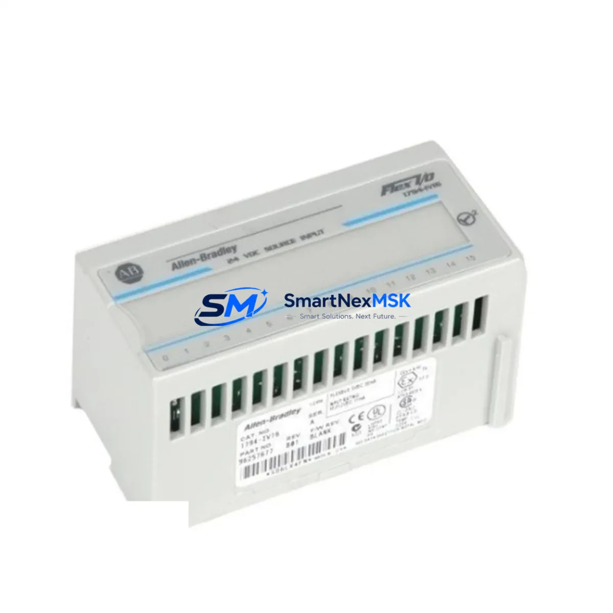
Allen-Bradley 1794-IV16 Retrofit-Ready Digital Input Module for FLEX I/O Control Systems
The Allen-Bradley 1794-IV16 is a 16-point, 24VDC sourcing digital input module designed for the FLEX I/O platform — one of Rockwell Automation’s most widely deployed distributed I/O architectures in process and discrete manufacturing environments. As legacy control systems age and OEM support windows close, the 1794-IV16 has become a critical retrofit component for engineers tasked with modernizing aging control cabinets without replacing the entire automation infrastructure.
Whether you are replacing a failed module on an active production line, upgrading a discontinued I/O rack, or migrating from an older Allen-Bradley SLC 500 or PLC-5 platform to a ControlLogix or CompactLogix architecture, the 1794-IV16 provides a proven, drop-in compatible solution that minimizes engineering rework and reduces commissioning time. SMARTNEXMSK maintains verified stock of the 1794-IV16 with full functional testing, 12-month warranty coverage, and same-week global dispatch.
Upgrade Compatibility Table
| Parameter | Specification / Retrofit Note |
|---|---|
| SKU / Part Number | 1794-IV16 |
| Platform | Allen-Bradley FLEX I/O (1794 Series) |
| Input Points | 16-point, 24VDC sourcing (IEC Type 1) |
| Backplane Interface | 1794 FLEX I/O adapter backplane (1794-ADN, 1794-AENT, 1794-ACN15) |
| Communication Compatibility | DeviceNet, EtherNet/IP, ControlNet (adapter-dependent) |
| Replaces / Upgrades | 1794-IV16, 1794-IV16XT (extended temp variant); compatible with SLC 500 and PLC-5 migration paths via ControlLogix bridge |
| Installation Requirement | Mounts on 1794 terminal base (1794-TB3, 1794-TB3S, 1794-TB32); no additional wiring adapter required for like-for-like replacement |
| Module Address | Configured via adapter; slot-based addressing in RSLogix 5000 / Studio 5000 |
| Commissioning Focus | Verify I/O tag mapping, input filter timing, and diagnostic bit configuration in controller program |
| Warranty | 12 Months — covers functional failure under normal operating conditions |
Retrofit Planning for Existing Automation Systems
Successful integration of the 1794-IV16 into an existing control system begins well before the module arrives on site. Engineers should start by auditing the current FLEX I/O rack configuration, confirming the installed adapter type — whether a 1794-ADN for DeviceNet, a 1794-AENT for EtherNet/IP, or a 1794-ACN15 for ControlNet — since the adapter determines the communication protocol and node addressing scheme for the entire I/O bank.
Terminal base selection is equally important. The 1794-IV16 is compatible with the 1794-TB3, 1794-TB3S, and 1794-TB32 terminal bases. In a like-for-like replacement, the existing terminal base can typically remain in place, preserving field wiring and eliminating the need to re-terminate 24VDC sensor cables. However, if the original terminal base shows signs of wear, corrosion, or damaged locking tabs, replacing it alongside the module is strongly recommended to ensure long-term connection integrity.
Power budget verification is a frequently overlooked step. Each FLEX I/O adapter has a defined backplane current capacity, and adding or replacing modules can shift the total draw. Before installing the 1794-IV16, confirm that the 1794 power supply — often a 1794-PS13 or equivalent — has sufficient headroom to support the module’s 24VDC backplane current requirement alongside other installed modules such as 1794-OB16 output modules, 1794-IE8 analog input modules, or 1794-OE4 analog output modules sharing the same rack.
For systems migrating from SLC 500 or PLC-5 platforms, the 1794-IV16 is commonly deployed as part of a distributed I/O expansion strategy using a ControlLogix chassis with a 1756-DNB DeviceNet scanner or a 1756-ENBT EtherNet/IP bridge module. In these migration scenarios, the I/O tag structure in the legacy program must be remapped to the new Logix tag-based addressing format in Studio 5000. Engineers should export the existing I/O configuration from RSLogix 500 or RSLogix 5, cross-reference the input bit assignments, and rebuild the tag database before going live. HMI screens built in PanelView or FactoryTalk View must also be updated to reflect the new tag paths, particularly for status indicators and alarm triggers tied to digital input states from the 1794-IV16.
Communication link verification should be performed with the network live but the controller in Program mode. Use RSLinx Classic or Studio 5000 Logix Designer to browse the I/O tree, confirm the 1794-IV16 appears at the correct slot address, and verify that all 16 input bits are reading correctly against known field signal states before switching to Run mode.
Downtime Control During System Migration
Minimizing unplanned downtime during a FLEX I/O module replacement requires a structured hot-swap or planned-outage strategy. The 1794 platform supports module removal and insertion under power (RIUP) in most configurations, allowing the 1794-IV16 to be swapped without de-energizing the entire I/O rack — a significant advantage in continuous-process environments where adjacent I/O points must remain active during the replacement.
Before initiating the swap, place the controller in Program mode to inhibit output execution while preserving the program in memory. This protects downstream actuators connected to 1794-OB16 or 1794-OB32 output modules from receiving unintended commands during the transition. Document the current input states from the HMI or SCADA system so that operators can manually monitor field conditions during the brief window when the module is offline.
After installing the replacement 1794-IV16, allow the adapter to re-enumerate the module — typically within 5 to 15 seconds on EtherNet/IP or DeviceNet networks. Confirm that the module status LED shows solid green and that no inhibit or fault bits are set in the controller’s I/O tree. Perform a point-by-point input verification by activating each field sensor or switch and confirming the corresponding input bit toggles correctly in the controller tag database before returning the system to Run mode.
For planned maintenance windows, pre-staging the replacement 1794-IV16 with a bench test using a 1747-UIC or 1784-U2DHP programming cable connected to a test rack can further compress on-site commissioning time. Pre-verified modules reduce the risk of discovering configuration issues during a live outage, protecting both production continuity and operator safety.
Retrofit Support FAQ
Q1: Is the 1794-IV16 a direct drop-in replacement for a failed unit in an existing FLEX I/O rack?
Yes. The 1794-IV16 is a like-for-like replacement within the 1794 FLEX I/O platform. It mounts on the same 1794-TB3 or 1794-TB3S terminal base, uses the same backplane connector, and requires no changes to the controller program or I/O configuration in Studio 5000 or RSLogix 5000, provided the replacement module is the same catalog number and firmware revision is compatible with the installed adapter.
Q2: What wiring changes are required when replacing the 1794-IV16?
In a like-for-like replacement using the existing terminal base, no field wiring changes are required. All 24VDC sensor connections remain on the terminal base and transfer automatically to the new module. If the terminal base is also being replaced, re-termination of field wiring is necessary — label all wires before removal and follow the 1794-IV16 wiring diagram in Rockwell publication 1794-IN006.
Q3: Does SMARTNEXMSK test the 1794-IV16 before shipment?
Yes. Every 1794-IV16 unit shipped by SMARTNEXMSK undergoes functional verification testing prior to dispatch, including backplane communication check, input point actuation test, and LED status confirmation. Each unit is covered by a 12-month warranty against functional failure under normal operating conditions. Expedited shipping options are available for urgent production-line recovery situations.
Q4: Can the 1794-IV16 be used in a migration from SLC 500 to ControlLogix?
Yes. The 1794-IV16 is widely used in SLC 500 to ControlLogix migration projects as part of a distributed FLEX I/O node connected via a 1756-DNB DeviceNet scanner or 1756-ENBT EtherNet/IP bridge. The key migration steps include remapping I/O tags from the SLC file-based addressing to Logix tag-based addressing in Studio 5000, updating HMI tag references in FactoryTalk View or PanelView, and verifying communication node addresses on the DeviceNet or EtherNet/IP network segment.
© 2026 SMARTNEXMSK. All rights reserved.
Original Source: https://smartnexmsk.com
Contact: [email protected] | +86 18259474341



