
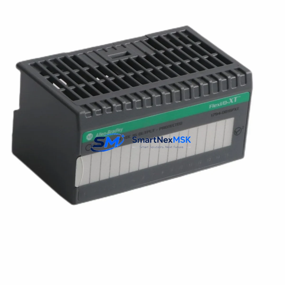
Allen-Bradley 1794-OB16PXT Retrofit-Ready Digital Output for FLEX I/O Control Systems
The Allen-Bradley 1794-OB16PXT is a 16-point, 24VDC sourcing digital output module designed for the FLEX I/O platform — one of Rockwell Automation’s most widely deployed distributed I/O architectures in process and discrete manufacturing environments. As legacy FLEX I/O installations age and original modules reach end-of-life, the 1794-OB16PXT remains a critical retrofit component for engineers tasked with sustaining production continuity without full system replacement.
This module mounts directly onto a 1794-TB3 or 1794-TB3S terminal base, occupying a single slot on the FLEX I/O backplane. It communicates with the host controller — typically a ControlLogix, CompactLogix, or SLC 500 platform — through an adapter such as the 1794-AENT (EtherNet/IP), 1794-ADN (DeviceNet), or 1794-APB (PROFIBUS DP). Before installation, engineers must verify that the adapter’s I/O tree configuration in Studio 5000 Logix Designer or RSLogix 5000 correctly maps the module’s output data table to the corresponding controller tags. Mismatched module addressing or incorrect slot numbering in the I/O configuration will prevent the controller from recognizing the replacement module and may trigger a major fault.
Power capacity planning is essential during any FLEX I/O retrofit. The 1794-OB16PXT draws current from the backplane power bus, and the total current budget across all modules on a given adapter segment must not exceed the adapter’s rated capacity. When replacing multiple failed output modules simultaneously — for example, swapping out both a 1794-OB16PXT and an adjacent 1794-IB16 input module — engineers should recalculate the cumulative backplane current draw and confirm that the 1794-PS13 or equivalent power supply can sustain the load. Undersized power supplies are a common root cause of intermittent faults in aging FLEX I/O panels.
Terminal wiring on the 1794-TB3 base follows a fixed pinout. Each of the 16 output channels connects to a dedicated terminal, with a shared 24VDC supply and common return. When the original module has been in service for many years, terminal screws may be corroded or torqued beyond specification. It is recommended to re-torque all terminals to the manufacturer’s specification (typically 0.5–0.6 N·m) and inspect for insulation damage before commissioning the replacement 1794-OB16PXT. Field wiring does not need to be disturbed if the terminal base remains in place — this is one of the key advantages of the FLEX I/O modular design.
Program compatibility is generally maintained when replacing a like-for-like module. The controller program references output tags by slot address and data type, not by physical module serial number. However, if the original module was configured with output fault states or program-controlled output holds, these parameters must be re-verified in the module’s properties dialog within Studio 5000. Confirm that the fault mode (hold last state vs. de-energize) matches the process safety requirements before returning the system to automatic operation.
HMI screens connected via FactoryTalk View SE or FactoryTalk View ME that display output status for the 1794-OB16PXT channels should be tested after replacement to confirm that tag bindings remain intact and that status indicators reflect actual field conditions. In some installations, HMI displays reference module diagnostic tags that may need to be re-subscribed if the module was offline for an extended period.
For systems migrating from older SLC 500-based FLEX I/O networks to a ControlLogix backbone, the 1794-OB16PXT can be retained in the field while the adapter is upgraded from a 1794-ASB (Remote I/O) to a 1794-AENT (EtherNet/IP). This adapter swap enables the existing I/O wiring and terminal bases to remain unchanged while the communication protocol is modernized — significantly reducing migration cost and downtime compared to a full panel replacement.
Upgrade Compatibility Table
| Parameter | Detail |
|---|---|
| SKU / Part Number | 1794-OB16PXT |
| Platform | Allen-Bradley FLEX I/O |
| Output Points | 16-point, 24VDC sourcing |
| Terminal Base Required | 1794-TB3 / 1794-TB3S |
| Compatible Adapters | 1794-AENT, 1794-ADN, 1794-APB, 1794-ASB |
| Compatible Controllers | ControlLogix, CompactLogix, SLC 500 |
| Programming Software | Studio 5000 Logix Designer, RSLogix 5000, RSLogix 500 |
| Backplane Current Draw | Verify against adapter segment budget |
| Installation Type | Drop-in replacement (same terminal base) |
| Communication Protocol | EtherNet/IP, DeviceNet, PROFIBUS DP, Remote I/O |
| Retrofit Recommendation | Retain terminal base; replace module only |
| Commissioning Check | Slot address, fault mode, HMI tag binding |
| Warranty | 12-Month Warranty included |
Retrofit Planning for Existing Automation Systems
A successful 1794-OB16PXT retrofit begins well before the replacement module arrives on site. The engineering team should pull the existing I/O configuration report from Studio 5000 and document the slot assignments for every module on the affected adapter segment. In a typical FLEX I/O panel supporting a packaging or conveyor line, this segment may include a mix of the 1794-IB16 (16-point 24VDC input), 1794-OB16 (standard output), 1794-OW8 (relay output), and 1794-IE8 (analog input) modules alongside the 1794-OB16PXT. Understanding the full slot map prevents addressing conflicts when the replacement module is inserted.
The 1794-AENT adapter’s web interface provides a live view of module status across the segment, which is useful for pre-retrofit diagnostics. Engineers can identify whether the fault is isolated to the 1794-OB16PXT or whether adjacent modules — such as the 1794-IB16 or the 1794-OB16 — are also reporting errors. This triage step avoids the common mistake of replacing a single module only to discover that the root cause was a failing 1794-PS13 power supply or a loose backplane connector.
For panels that include a 1794-ACN15 ControlNet adapter or a 1794-ACNR15 redundant ControlNet adapter, the network schedule must be updated in RSNetWorx for ControlNet after the module replacement to ensure the new module is included in the scheduled connection. Failure to update the network schedule is a frequent commissioning oversight that results in the controller reporting a connection timeout fault even though the module is physically installed and powered.
When the retrofit scope extends to upgrading the communication infrastructure — for example, replacing a 1794-ASB Remote I/O adapter with a 1794-AENT EtherNet/IP adapter — the controller program must be updated to use explicit messaging or produced/consumed tags in place of the legacy block transfer instructions used with Remote I/O. This program modification should be developed and tested in an offline simulation environment before being applied to the live system. A 1747-UIC USB-to-DH+ interface cable or a 1784-U2DHP adapter may be required to maintain connectivity to the SLC 500 controller during the transition period.
Downtime Control During System Migration
Minimizing unplanned downtime during a 1794-OB16PXT replacement requires a structured approach to pre-staging, execution, and verification. The replacement module should be bench-tested before the maintenance window using a spare 1794-TB3 terminal base and a portable 24VDC power supply to confirm that all 16 output channels energize correctly and that the module’s status LED sequence matches the expected power-up behavior.
During the maintenance window, the controller should be placed in Program mode before the module is removed. This prevents the controller from generating a major fault due to a lost I/O connection and allows the existing program logic to be preserved in memory. The 1794-OB16PXT can then be removed from the terminal base by releasing the module latch — no tools required — and the replacement module inserted. The controller can be returned to Run mode once the I/O configuration has been verified and the module status LED indicates a healthy connection.
For critical processes where even a brief interruption is unacceptable, a hot-swap strategy can be considered if the FLEX I/O adapter supports it. The 1794-AENT adapter supports partial fault recovery, allowing a replacement module to be inserted while the adapter remains online. However, this approach requires careful coordination with the control system engineer to ensure that the output channels are inhibited in the controller program before the swap and re-enabled only after the replacement module has been confirmed healthy.
Maintaining a documented record of the pre-swap and post-swap I/O status — including the state of all 16 output channels, the module’s diagnostic counters, and the controller’s I/O fault log — provides a clear audit trail for maintenance records and supports future troubleshooting. This documentation is particularly valuable in regulated industries where change management procedures require evidence that the replacement did not alter the system’s functional behavior.
Retrofit Support FAQ
Q: Is the 1794-OB16PXT a direct drop-in replacement for the 1794-OB16?
A: The 1794-OB16PXT and 1794-OB16 share the same 16-point 24VDC sourcing output architecture and use the same 1794-TB3 terminal base, making the swap mechanically and electrically compatible in most applications. The key difference is that the 1794-OB16PXT includes extended temperature ratings suitable for harsh environments. Verify the module properties in Studio 5000 to confirm that the electronic keying setting is set to “Compatible Module” or “Disable Keying” to allow the replacement to be accepted by the controller without a configuration mismatch fault.
Q: What wiring changes are required when installing the 1794-OB16PXT?
A: If the 1794-TB3 terminal base is already installed and the field wiring is intact, no wiring changes are required. The module slides into the terminal base without disturbing the terminal connections. If the terminal base is being replaced at the same time, re-terminate all field wiring according to the original wiring diagram and re-torque terminals to specification before powering up.
Q: How do I verify communication compatibility with my existing adapter?
A: The 1794-OB16PXT is compatible with all standard FLEX I/O adapters, including the 1794-AENT (EtherNet/IP), 1794-ADN (DeviceNet), 1794-APB (PROFIBUS DP), and 1794-ASB (Remote I/O). After installation, use the adapter’s web interface or the controller’s I/O diagnostics in Studio 5000 to confirm that the module is recognized at the correct slot address and that no connection faults are reported.
Q: What does the 12-month warranty cover?
A: Every 1794-OB16PXT supplied by SMARTNEXMSK includes a 12-month warranty covering manufacturing defects and functional failures under normal operating conditions. Each unit undergoes pre-shipment functional testing to verify output channel operation, backplane communication, and LED status indication. Warranty claims are supported by our technical team at [email protected].
© 2026 SMARTNEXMSK. All rights reserved.
Original Source: https://smartnexmsk.com
Contact: [email protected] | +86 18259474341



