
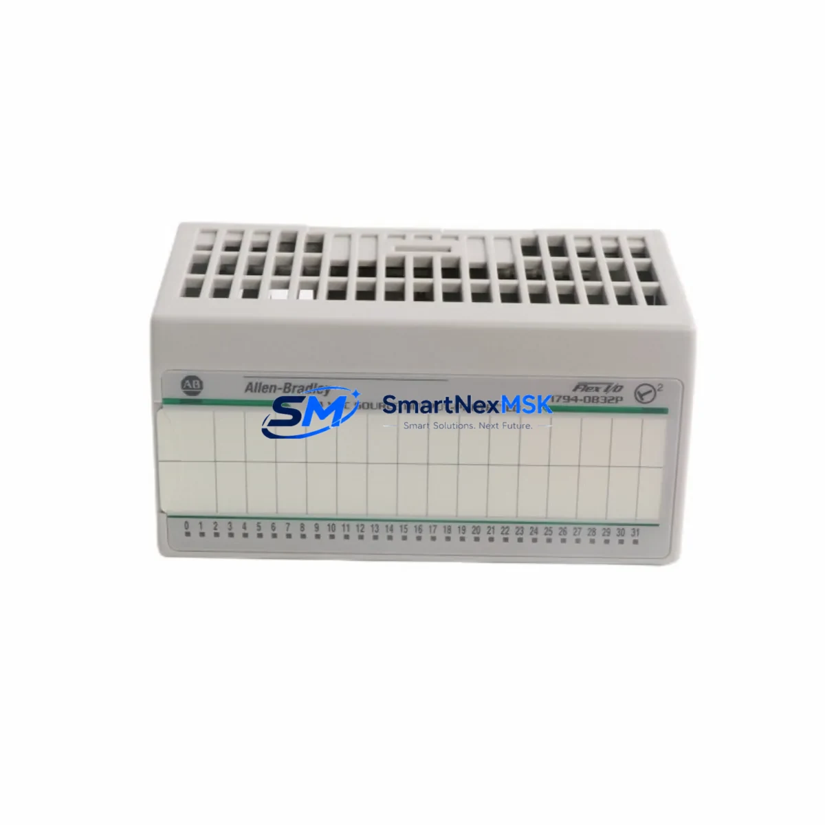
Allen-Bradley 1794-OB32P Retrofit-Ready Output for FLEX I/O Control Systems
The Allen-Bradley 1794-OB32P is a 32-point, 24VDC sourcing digital output module designed for the FLEX I/O platform — one of Rockwell Automation’s most widely deployed distributed I/O architectures in legacy and active production environments. As original equipment reaches end-of-life or becomes increasingly difficult to source through standard channels, the 1794-OB32P remains a critical retrofit and replacement component for engineers managing aging control cabinets, panel upgrades, and system modernization projects.
This module mounts directly onto the 1794-TB3 or 1794-TB3S terminal base, providing 32 individually fused sourcing outputs rated at 0.5A per point and 8A per common. Its compact form factor and backplane compatibility with the FLEX I/O adapter — including the 1794-AENT, 1794-ACNR15, and 1794-ADN — make it a preferred choice for engineers who need to restore output capacity without redesigning the entire I/O architecture. The 1794-OB32P is fully compatible with ControlLogix, CompactLogix, and SLC 500 control platforms when paired with the appropriate adapter module.
Upgrade Compatibility Table
| Parameter | 1794-OB32P Specification | Retrofit Notes |
|---|---|---|
| Output Points | 32 sourcing (PNP), 24VDC | Verify field device polarity before wiring |
| Current per Point | 0.5A max | Check actuator inrush current ratings |
| Terminal Base | 1794-TB3 / 1794-TB3S | Existing terminal base can be reused if undamaged |
| Backplane Interface | FLEX I/O backplane | Compatible with all 1794-series adapters |
| Communication Adapters | 1794-AENT, 1794-ACNR15, 1794-ADN | Adapter firmware update may be required |
| Controller Compatibility | ControlLogix, CompactLogix, SLC 500 | Verify I/O tree mapping in RSLogix / Studio 5000 |
| Module Address | Slot-based, auto-configured | Confirm slot assignment matches existing program tags |
| Installation | DIN rail or panel mount via terminal base | No additional mounting hardware required |
| Commissioning | Force outputs in Studio 5000 / RSLogix 5000 | Test each output point before full restart |
| Warranty | 12-Month Warranty | Covers manufacturing defects; includes pre-shipment functional test |
Retrofit Planning for Existing Automation Systems
When integrating the 1794-OB32P into an existing FLEX I/O drop, the first step is a thorough audit of the current terminal base condition. If the 1794-TB3 terminal base shows signs of terminal wear, corrosion, or damaged locking tabs, it should be replaced concurrently to avoid intermittent contact faults after commissioning. The module slides directly into the terminal base and locks into the backplane without tools, but the wiring side requires careful attention to the 32-point output commons and their associated fuse groups.
Power supply capacity is a frequent oversight in retrofit projects. The 1794-OB32P draws current from both the backplane logic supply and the field-side 24VDC power rail. Engineers should verify that the existing 1794-PS13 or equivalent FLEX I/O power supply can support the additional load, particularly when replacing a failed module in a fully loaded I/O drop. If the power budget is marginal, a supplemental 24VDC supply or a power supply upgrade should be planned before the cutover window.
For systems communicating over EtherNet/IP via the 1794-AENT adapter, no protocol migration is required — the 1794-OB32P is natively recognized by the adapter and appears in the I/O tree as a standard output module. However, if the existing system uses a 1794-ACNR15 ControlNet adapter or a 1794-ADN DeviceNet adapter, engineers should confirm that the adapter’s node address and network configuration remain unchanged after the module swap. In some cases, a 1794-ACN15 ControlNet adapter firmware update is necessary to maintain compatibility with newer module revisions.
HMI screens tied to output status indicators — particularly those built on PanelView Plus or FactoryTalk View SE — should be reviewed to confirm that tag bindings reference the correct controller tags rather than hardcoded I/O addresses. If the original program was developed in RSLogix 5000 with aliased tags, the retrofit is typically transparent to the HMI layer. For older SLC 500-based systems migrating to a CompactLogix platform, a full tag remapping exercise is recommended, and the 1794-OB32P’s output data file structure should be mapped to the new controller’s output tags during the pre-commissioning phase.
I/O expansion during the retrofit is also a common requirement. If the control cabinet needs additional input capacity alongside the output replacement, the 1794-IB32 or 1794-IB16 input modules can be added to the same FLEX I/O drop without requiring a new adapter or backplane segment. Similarly, if analog I/O is needed for process control loops, the 1794-IE8 or 1794-OE8 analog modules integrate seamlessly into the same rack. For systems requiring safety-rated I/O, the 1791DS-IB8XOBV4 safety module should be evaluated as a separate, dedicated safety drop rather than mixing standard and safety I/O on the same adapter.
Downtime Control During System Migration
Minimizing unplanned downtime is the primary concern in any live production retrofit. For the 1794-OB32P replacement, the recommended approach is a pre-staged swap: the replacement module is tested on a bench setup or spare terminal base before the maintenance window begins, confirming that the module powers up correctly and responds to forced output commands from the programming terminal.
During the cutover, the controller should be placed in Program mode rather than powered down entirely, preserving the program in controller memory and reducing restart time. The existing terminal base wiring can remain intact if the 1794-TB3 is being reused — only the module itself needs to be removed and replaced. After seating the new 1794-OB32P, the controller can be returned to Run mode and outputs verified sequentially using the Studio 5000 or RSLogix 5000 I/O forcing function before releasing control back to the program.
For systems where a cold restart is unavoidable, a pre-documented restart sequence — including the order in which field devices should be re-energized, the expected HMI alarm states during startup, and the communication link verification steps for the 1794-AENT or 1794-ADN adapter — significantly reduces the risk of extended downtime. All 1794-OB32P units supplied by SMARTNEXMSK undergo a pre-shipment functional test to confirm output switching, backplane communication, and LED status indication before dispatch, ensuring that the replacement module is field-ready upon arrival.
Retrofit Support FAQ
Q: Is the 1794-OB32P a direct drop-in replacement for the 1794-OB32?
A: The 1794-OB32P is the protected (fused) variant of the 1794-OB32. Both modules use the same 1794-TB3 terminal base and occupy the same backplane slot. The primary difference is the per-point electronic fusing on the OB32P, which provides additional field-side protection. In most applications, the OB32P is a direct functional replacement for the OB32, and no program changes are required.
Q: Do I need to reconfigure the adapter after replacing the module?
A: In most cases, no. The 1794-AENT, 1794-ACNR15, and 1794-ADN adapters automatically detect the module type during power-up. If the replacement module is the same catalog number as the original, the adapter configuration remains valid. If the module revision has changed, a minor configuration update in RSLogix 5000 or Studio 5000 may be required to acknowledge the new revision.
Q: What pre-shipment testing is performed on the 1794-OB32P?
A: Each unit undergoes a functional output switching test, backplane communication verification, and LED status check before shipment. Units are supplied with a 12-month warranty covering manufacturing defects. Test records are available upon request for quality-critical applications.
Q: Can the 1794-OB32P be used in a system currently running on an SLC 500 platform?
A: Yes, when paired with a compatible FLEX I/O adapter such as the 1794-ASB or 1794-AENT, the 1794-OB32P can be integrated into SLC 500-based systems. For full SLC 500 compatibility, verify the adapter type and confirm that the I/O configuration in RSLogix 500 matches the module’s output data file structure.
© 2026 SMARTNEXMSK. All rights reserved.
Original Source: https://smartnexmsk.com
Contact: [email protected] | +86 18259474341



