
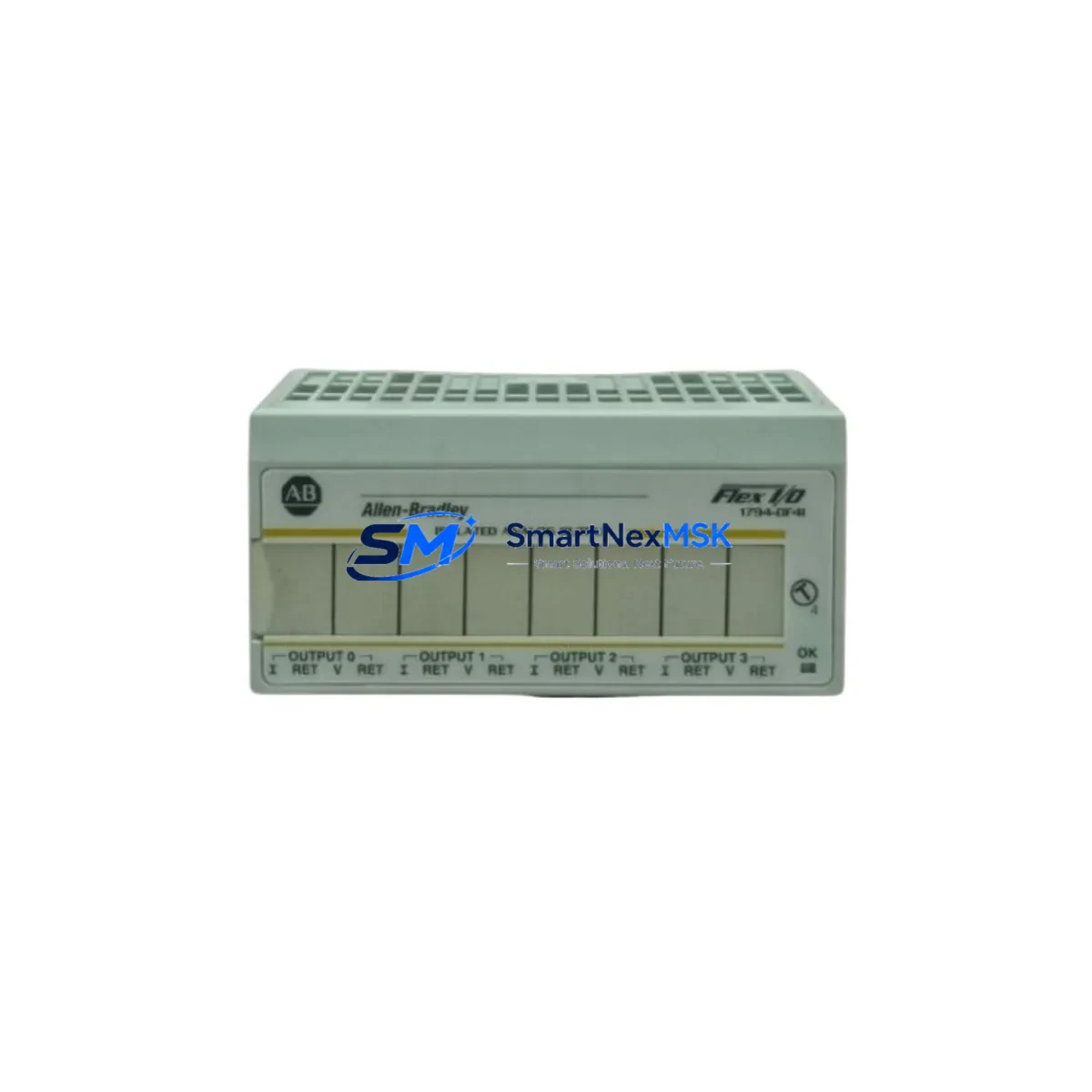
Allen-Bradley 1794-OF4I Retrofit-Ready Analog Output for FLEX I/O Control Systems
The Allen-Bradley 1794-OF4I is a 4-channel isolated analog output module designed for the FLEX I/O platform — one of Rockwell Automation’s most widely deployed distributed I/O architectures in process and discrete manufacturing environments. As legacy control systems age and original spare parts become increasingly difficult to source, the 1794-OF4I has become a critical retrofit component for engineers tasked with modernizing aging control cabinets without full system replacement.
This module outputs 4–20 mA or 0–10 VDC signals across four fully isolated channels, making it suitable for driving control valves, variable frequency drives, and analog-input field instruments. Its channel isolation architecture prevents ground loop interference — a common failure mode in older panel wiring — and simplifies compliance with updated electrical safety standards during retrofit projects.
When replacing a failed or end-of-life 1794-OF4I in an existing FLEX I/O rack, engineers must verify the 1794-ADN or 1794-ADNK DeviceNet adapter (or the 1794-AENT EtherNet/IP adapter in newer installations) is firmware-compatible with the replacement module. The module occupies a single slot on the 1794-TB3 or 1794-TB3S terminal base — confirm the terminal base is present and undamaged before installation, as the terminal base is not included with the module and must be ordered separately if missing.
Upgrade Compatibility Table
| Parameter | Detail |
|---|---|
| SKU / Part Number | 1794-OF4I |
| Platform | Allen-Bradley FLEX I/O |
| Output Channels | 4 (fully isolated) |
| Output Signal | 4–20 mA / 0–10 VDC (configurable per channel) |
| Terminal Base Required | 1794-TB3 or 1794-TB3S (ordered separately) |
| Compatible Adapters | 1794-ADN (DeviceNet), 1794-AENT (EtherNet/IP), 1794-ACN15 (ControlNet) |
| Backplane Interface | FLEX I/O backplane (1-slot) |
| Power Consumption | Verify adapter power budget before installation |
| Common Replacement For | 1794-OF4, 1794-OF4I (earlier revisions), legacy analog output cards |
| Installation Requirement | RSLogix 5000 / Studio 5000 I/O configuration update required |
| Communication Protocol | DeviceNet / EtherNet/IP / ControlNet (adapter-dependent) |
| Commissioning Tool | RSNetWorx for DeviceNet or Studio 5000 Logix Designer |
| Warranty | 12 Months |
Retrofit Planning for Existing Automation Systems
Successful integration of the 1794-OF4I into an existing control system requires a structured pre-installation review. Begin by auditing the current FLEX I/O rack configuration: document the slot assignment of the failed module, the adapter type in use, and the total power draw across all installed modules. The 1794-ADN DeviceNet adapter has a defined power budget for the I/O modules it supports — adding or replacing modules without recalculating this budget is a common cause of intermittent faults after retrofit.
Next, review the RSLogix 5000 or Studio 5000 project file. The 1794-OF4I must be added to the I/O tree under the correct adapter node, and its module definition — including revision, electronic keying setting, and output data format — must match the physical hardware. If the project was originally configured for an earlier revision of the 1794-OF4I or for the non-isolated 1794-OF4, the module definition will need to be updated. Set electronic keying to “Compatible Module” during initial commissioning to avoid keying faults if minor revision differences exist between the replacement unit and the original configuration.
Terminal wiring should be mapped against the existing field wiring schedule before disconnecting any cables. The 1794-TB3 terminal base uses a removable wiring assembly, which allows the field wiring to remain connected while the module is swapped — a significant advantage for minimizing downtime in live production environments. Label all field wires before removal and photograph the terminal layout as a reference.
For systems using a 1794-AENT EtherNet/IP adapter, verify the IP address configuration and confirm the ControlLogix or CompactLogix controller — such as a 1756-L71 or 1769-L33ER — has the correct I/O connection path defined. If the system includes a PanelView Plus HMI displaying analog output values or setpoints, update the HMI tag bindings after the module replacement to ensure display accuracy. In some older installations, HMI screens reference module-specific tags that may need remapping if the module slot or data format changes.
Where the retrofit involves migrating from an older SLC 500 or PLC-5 analog output card to the FLEX I/O platform, additional steps are required: the legacy 1746-NO4I (SLC 500 analog output) or 1771-OFE (PLC-5 analog output) must be decommissioned, and the field wiring re-terminated to the 1794-TB3 terminal base. Signal scaling parameters in the controller program will also need to be reconfigured to match the 1794-OF4I’s output data format. A 1747-UIC or 1784-U2DHP programming cable may be needed to access the legacy controller during the transition phase.
Downtime Control During System Migration
Minimizing unplanned downtime is the primary operational concern during any analog output module replacement. The recommended approach is to pre-stage the replacement 1794-OF4I with its terminal base, verify the module powers up correctly on a bench test rack (such as a spare 1794-ADN adapter with a bench power supply), and confirm the output signals are within specification before bringing the unit to the field.
In the controller program, place the affected analog output channels in a safe “hold last value” or “go to failsafe” state before disconnecting the failed module. This prevents downstream actuators — valves, drives, or positioners — from receiving erratic signals during the swap. If the process cannot tolerate any output interruption, coordinate with operations to place the affected loop in manual control at the DCS or HMI level before proceeding.
Once the replacement module is installed and the terminal base wiring is reconnected, bring the controller online and monitor the I/O status in Studio 5000. Confirm the module status indicator shows a solid green light and that no faults are present in the controller fault log. Perform a live output check by commanding each channel to a known value and verifying the corresponding field signal with a calibrated loop calibrator. Document the as-found and as-left readings for the maintenance record. Total swap time for a prepared technician with pre-staged hardware is typically under 30 minutes, keeping production impact to a minimum.
Retrofit Support FAQ
Q: Is the 1794-OF4I a direct drop-in replacement for the 1794-OF4?
A: The 1794-OF4I is the isolated version of the 1794-OF4. Both use the same 1794-TB3 terminal base and occupy one FLEX I/O slot. However, the I/O data format and module definition in RSLogix 5000 / Studio 5000 differ between the two models. You must update the module definition in your controller project to match the 1794-OF4I. Electronic keying should be set to “Compatible Module” during initial commissioning.
Q: What wiring changes are required when installing the 1794-OF4I?
A: If you are replacing a same-model 1794-OF4I, no wiring changes are required — the 1794-TB3 terminal base retains the existing field wiring. If migrating from a different analog output platform (e.g., 1746-NO4I or 1771-OFE), field wiring must be re-terminated to the 1794-TB3 terminal base according to the 1794-OF4I wiring diagram. Verify signal polarity and loop power configuration for each channel before energizing.
Q: How do I verify communication after installation?
A: After installing the module, go online with Studio 5000 Logix Designer and navigate to the I/O tree. The 1794-OF4I should appear under its adapter node with a green status indicator. Use the “Module Properties” dialog to confirm the connection is established. For DeviceNet systems, use RSNetWorx for DeviceNet to verify the node address and confirm the module is communicating on the network. Check the controller’s I/O fault log for any connection errors.
Q: What does the 12-month warranty cover?
A: Our 12-month warranty covers manufacturing defects and functional failures under normal operating conditions. Each unit is tested for output signal accuracy and channel isolation before shipment. The warranty does not cover damage caused by incorrect installation, overvoltage, or environmental conditions outside the module’s rated specifications. Contact [email protected] for warranty claims or pre-shipment test reports.
© 2026 SMARTNEXMSK. All rights reserved.
Original Source: https://smartnexmsk.com
Contact: [email protected] | +86 18259474341



