
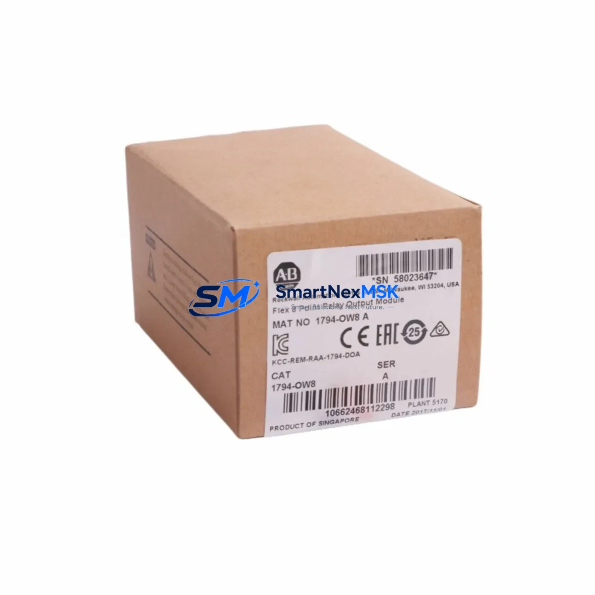
Allen-Bradley 1794-OW8 Spare for FLEX I/O Automation
The Allen-Bradley 1794-OW8 is an 8-point relay output module designed for the FLEX I/O distributed I/O platform. As a maintenance-ready original spare, it enables rapid replacement in the event of relay contact failure, output signal loss, or scheduled preventive maintenance — minimizing unplanned downtime and restoring control system continuity with confidence. Each unit supplied by SMARTNEXMSK is sourced from verified channels, functionally tested prior to dispatch, and backed by a 12-month warranty.
For maintenance engineers managing Allen-Bradley FLEX I/O racks, the 1794-OW8 is a critical component in discrete output circuits controlling solenoids, motor starters, pilot lights, and small actuators. Its relay contact architecture provides galvanic isolation between the control logic and field devices — a key advantage in environments with inductive loads or mixed voltage levels. Holding a qualified spare on the shelf eliminates the risk of extended lead times disrupting production schedules.
Procurement engineers sourcing replacement modules for aging FLEX I/O systems will find the 1794-OW8 fully compatible with existing 1794 terminal base assemblies, including the 1794-TB3, 1794-TB3S, and 1794-TB32 series. No firmware reconfiguration is required when replacing a like-for-like module in an established RSLogix 5000 or Studio 5000 project, making field swap-out straightforward and low-risk.
Spare Maintenance Table
| Parameter | Specification |
|---|---|
| Part Number / SKU | 1794-OW8 |
| Series / Platform | Allen-Bradley FLEX I/O (1794 Series) |
| Module Type | 8-Point Relay Output Module |
| Output Type | Relay (Form A / SPST-NO contacts) |
| Points per Module | 8 isolated relay outputs |
| Output Voltage Range | 5–125V DC / 5–240V AC |
| Max Output Current | 2A per point (resistive load) |
| Isolation | Galvanic isolation between logic and field side |
| Compatible Terminal Bases | 1794-TB3, 1794-TB3S, 1794-TB32, 1794-TB3T |
| Communication Interface | Via FLEX I/O adapter (e.g. 1794-AENT, 1794-ACN15) |
| Compatible Software | RSLogix 5000, Studio 5000 Logix Designer |
| Operating Temperature | 0°C to 55°C (32°F to 131°F) |
| Mounting | DIN rail via 1794 terminal base |
| Approvals | UL, CE, cUL |
| Origin | United States |
| Condition | Original, new or reconditioned — tested before shipment |
| Warranty | 12 Months |
Maintenance Planning for Continuous Operation
When replacing the 1794-OW8 during a planned or emergency maintenance event, a thorough inspection of the surrounding control cabinet components is strongly recommended. Relay output failures are rarely isolated — they often indicate stress on adjacent modules or upstream power distribution components.
Begin by verifying the 1794-TB3 or 1794-TB32 terminal base for signs of arc damage, loose field wiring, or corroded terminals. A degraded terminal base can cause intermittent contact faults that mimic module failure. Next, inspect the 1794-AENT or 1794-ACN15 FLEX I/O adapter — the communication backbone of the rack — for firmware currency and network health indicators. A faulty adapter can mask output faults or generate false diagnostics.
Check the 1794-PS13 or 1794-PS1 power supply module supplying the FLEX I/O rack. Voltage sag or ripple on the 24V DC bus is a common root cause of relay contact chatter and premature contact wear. Use a calibrated multimeter or power quality analyzer to confirm rail stability before commissioning the replacement 1794-OW8.
For mixed I/O racks, also audit the 1794-IB16 or 1794-IA8 input modules sharing the same backplane. Backplane communication errors can cause output modules to latch in a fault state. If the system includes analog loops, verify the 1794-IE8 analog input module and any associated signal isolators or loop-powered transmitters for correct scaling and grounding.
In cabinets with motor control circuits, inspect the interposing relay assemblies and fuse terminal blocks downstream of the 1794-OW8 outputs. Blown fuses or welded relay contacts in the field circuit can back-feed voltage onto the module’s output terminals, causing damage to the replacement unit if not cleared before installation. Finally, review the 1794-OB16 or 1794-OB8EP transistor output modules in adjacent slots — if the application mixes relay and solid-state outputs, ensure load segregation is maintained per the original panel design.
Site Replacement Workflow
Step 1 — Isolate and de-energize: Follow your site LOTO (Lockout/Tagout) procedure. Remove field wiring from the terminal base only if the base itself is being replaced; the 1794-OW8 module slides out of the terminal base without disturbing field wiring, which significantly reduces replacement time and re-commissioning risk.
Step 2 — Module extraction: Release the module locking tab on the 1794 terminal base and slide the 1794-OW8 straight out. Inspect the backplane connector pins for damage or contamination before inserting the replacement unit.
Step 3 — Insert replacement: Align the replacement 1794-OW8 with the terminal base guide rails and press firmly until the locking tab engages. No tools are required. The module is keyed to prevent incorrect insertion.
Step 4 — Power-up and verify: Re-energize the rack and observe the module status LED. A solid green RUN indicator confirms successful backplane communication. In Studio 5000, verify the module’s I/O tree status and force a test output to confirm relay contact continuity on each of the 8 points before returning the system to automatic mode.
Step 5 — Documentation: Record the replacement date, module serial number, and any observed fault codes in your CMMS or maintenance log. This data supports future predictive maintenance scheduling and warranty claim processing if required.
Spare Parts Support FAQ
Q1: Is the 1794-OW8 still available as a new original part, or only as a reconditioned spare?
Both new original and professionally reconditioned units are available depending on current stock. All units — regardless of condition — undergo functional output testing across all 8 relay points before shipment. Condition is clearly stated on the order confirmation and shipping documentation.
Q2: How do I confirm compatibility with my existing FLEX I/O rack before ordering?
The 1794-OW8 is compatible with all standard 1794 series terminal bases (TB3, TB3S, TB32, TB3T) and any FLEX I/O adapter supporting the 1794 backplane protocol. Provide your adapter model (e.g. 1794-AENT, 1794-ACN15) and terminal base catalog number when contacting our technical team, and we will confirm compatibility before processing your order.
Q3: What does the 12-month warranty cover, and how is a warranty claim processed?
The 12-month warranty covers manufacturing defects and functional failures under normal operating conditions. It does not cover damage caused by incorrect installation, overvoltage, or environmental contamination beyond the module’s rated IP rating. To initiate a claim, contact [email protected] with your order number, a description of the fault, and any available diagnostic screenshots from Studio 5000. Replacement or repair is typically processed within 5–10 business days.
Q4: Can SMARTNEXMSK support long-term supply agreements for 1794-OW8 and related FLEX I/O spares?
Yes. For facilities managing multiple FLEX I/O installations or planning multi-year maintenance contracts, we offer blanket order arrangements with reserved stock allocation. This ensures priority access to critical spares such as the 1794-OW8, adapter modules, and terminal bases without exposure to spot-market lead time volatility. Contact our sales team to discuss volume pricing and consignment options.
© 2026 SMARTNEXMSK. All rights reserved.
Original Source: https://smartnexmsk.com
Contact: [email protected] | +86 18259474341



