
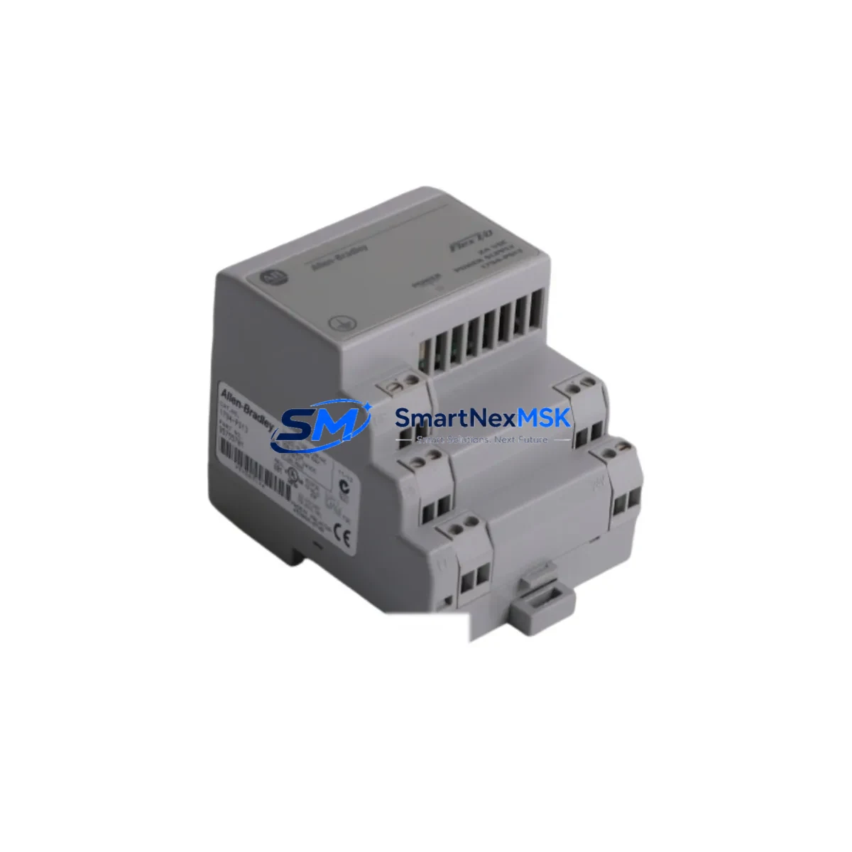
Allen-Bradley 1794-PS13 Spare for FLEX I/O Automation: Spare Replacement & Industrial Downtime Risk Control
The Allen-Bradley 1794-PS13 is a 24V DC input power supply module designed for the Rockwell Automation FLEX I/O platform. As a critical component in distributed I/O architectures, the 1794-PS13 provides regulated power to FLEX I/O adapter and terminal base assemblies, making it a high-priority spare in any industrial maintenance program. Whether you are managing a continuous process line, a packaging system, or a legacy PLC-5 or ControlLogix-integrated control cabinet, maintaining a verified replacement unit of the 1794-PS13 on the shelf is essential to minimizing unplanned downtime and protecting production continuity.
This listing supplies an original Allen-Bradley 1794-PS13 spare module, sourced from authorized channels, individually tested before shipment, and backed by a 12-month warranty. Each unit is verified for electrical integrity, connector condition, and firmware compatibility prior to dispatch, ensuring that your maintenance team receives a field-ready replacement without the uncertainty of grey-market sourcing.
Spare Maintenance Table
| Parameter | Specification |
|---|---|
| SKU / Part Number | 1794-PS13 |
| Brand | Allen-Bradley / Rockwell Automation |
| Series | FLEX I/O (1794 Series) |
| Module Type | Power Supply Module |
| Input Voltage | 24V DC |
| Output | Regulated 5V DC for FLEX I/O backplane |
| Compatible Adapters | 1794-AENT, 1794-ADN, 1794-ACN15, 1794-ACNR15 |
| Compatible Terminal Bases | 1794-TB3, 1794-TB3S, 1794-TB32, 1794-TBN |
| Installation | DIN rail or panel mount via FLEX I/O terminal base |
| Operating Temperature | 0°C to 55°C (32°F to 131°F) |
| Relative Humidity | 5% to 95% non-condensing |
| Application Environment | Industrial control panels, distributed I/O nodes, process automation |
| Compatibility | ControlLogix, CompactLogix, PLC-5, SLC 500 via FLEX I/O adapter |
| Condition | Original, tested before shipment |
| Warranty | 12 Months |
| Dispatch | Fast dispatch; DHL / FedEx / UPS available |
Maintenance Planning for Continuous Operation
When a 1794-PS13 power supply module fails or shows signs of degradation — such as intermittent I/O faults, adapter communication errors, or unexplained module resets — the root cause is often traced to insufficient backplane power delivery. Before replacing the 1794-PS13 in isolation, a thorough maintenance engineer will also inspect the surrounding components in the same FLEX I/O node and control cabinet to rule out cascading failures.
Start with the 1794-AENT EtherNet/IP adapter or the 1794-ADN DeviceNet adapter mounted on the same terminal base assembly. A failing power supply can cause the adapter to drop off the network, generating false communication faults that are often misdiagnosed as network infrastructure issues. Verify the adapter’s status LEDs and re-establish communication after the power supply is replaced.
Inspect the 1794-TB3 or 1794-TB3S terminal bases for signs of heat stress, discoloration, or loose wiring connections. Terminal bases in high-vibration environments are prone to micro-fractures in the connector housing, which can cause intermittent power interruptions that mimic power supply failures. Tighten all field wiring terminations and verify torque specifications per the installation manual.
Check the 24V DC input power rail feeding the 1794-PS13. Use a calibrated multimeter to confirm that input voltage is within the 18–32V DC operating range under load. Voltage sag caused by an undersized power supply — such as an aging 1606-XLP or 1606-XLS series power supply — can cause the 1794-PS13 to operate outside its design envelope, accelerating wear. If the cabinet power supply is more than five years old, schedule a proactive replacement as part of the same maintenance window.
For nodes running analog I/O modules such as the 1794-IE8 or 1794-OE4, verify signal accuracy after the power supply replacement. Analog modules are sensitive to backplane voltage stability; a marginal power supply can introduce offset errors or noise that affect process control accuracy without triggering a hard fault. Recalibrate analog channels as part of the post-replacement commissioning checklist.
If the FLEX I/O node includes 1794-IB16 or 1794-OB16 digital I/O modules, cycle power to the entire node after the 1794-PS13 replacement and verify that all I/O points respond correctly in the PLC program. Document the I/O map before and after replacement to confirm no address shifts have occurred.
For cabinets with signal isolators or loop-powered transmitters connected to the FLEX I/O analog inputs, inspect the isolator barriers and verify that 4–20 mA loop integrity is maintained after the power supply swap. Isolators from brands such as Phoenix Contact or Pepperl+Fuchs should be checked for proper grounding and shielding continuity.
Finally, review the fuse and circuit protection on the 24V DC input line to the 1794-PS13. A blown or weakened fuse is often the first indicator of a transient overcurrent event that may have damaged the power supply. Replace fuses with the correct rating and consider adding a surge protection device (SPD) on the DC bus if the installation environment is subject to switching transients from variable frequency drives or large contactors.
Site Replacement Workflow
Replacing the 1794-PS13 in the field is a straightforward procedure when the correct spare is on hand and the replacement workflow is followed systematically. Begin by placing the affected FLEX I/O node in a safe state: inhibit the adapter in the PLC program, set all outputs to a known safe condition, and de-energize the 24V DC input to the terminal base assembly. Do not attempt a hot-swap of the power supply module without confirming that the specific terminal base and adapter combination supports live insertion.
Remove the failed 1794-PS13 by releasing the module locking tab and sliding it out of the terminal base slot. Inspect the terminal base connector pins for damage, corrosion, or debris before installing the replacement unit. Insert the new 1794-PS13 firmly until the locking tab engages, then restore 24V DC power to the node. Verify that the module status LED illuminates green and that the adapter re-establishes communication with the PLC within the expected timeout period.
For legacy systems where the 1794-PS13 is part of a larger FLEX I/O rack supporting a PLC-5 or SLC 500 controller, confirm that the replacement module’s firmware revision is compatible with the existing adapter firmware. In some cases, a firmware mismatch between the power supply and adapter can cause initialization errors. Consult the Rockwell Automation compatibility matrix or contact your automation supplier for guidance.
After replacement, update the maintenance log with the module serial number, installation date, and test results. Schedule the next inspection interval based on the operating environment — typically 12 to 24 months for standard industrial environments, or 6 to 12 months for high-temperature or high-vibration applications. Maintaining a minimum of one spare 1794-PS13 unit in the local spare parts inventory is recommended for any facility operating more than three FLEX I/O nodes.
Spare Parts Support FAQ
Q1: Is this 1794-PS13 an original Allen-Bradley module or a compatible replacement?
This is an original Allen-Bradley 1794-PS13 module sourced from authorized supply channels. It is not a third-party compatible or counterfeit unit. Each module is individually tested before shipment to verify electrical performance and connector integrity.
Q2: What does the 12-month warranty cover?
The 12-month warranty covers manufacturing defects and electrical failures under normal operating conditions. It does not cover damage caused by incorrect installation, overvoltage events, or physical mishandling. Warranty claims are processed within 5 business days of receiving the returned unit, with a replacement dispatched promptly upon verification.
Q3: How do I confirm compatibility with my existing FLEX I/O system before ordering?
The 1794-PS13 is compatible with all standard 1794 Series FLEX I/O terminal bases and adapters, including EtherNet/IP, DeviceNet, ControlNet, and PROFIBUS variants. If your system uses a non-standard terminal base or a legacy adapter revision, please contact us with your existing module catalog number and firmware revision so we can confirm compatibility before dispatch.
Q4: What is your typical lead time and shipping process?
In-stock units are dispatched within 1–2 business days. International shipments are available via DHL Express, FedEx International Priority, or UPS Worldwide Expedited. Each shipment includes a test report and packing list. For urgent downtime recovery orders, please contact us directly to arrange same-day dispatch where available.
© 2026 SMARTNEXMSK. All rights reserved.
Original Source: https://smartnexmsk.com
Contact: [email protected] | +86 18259474341



