
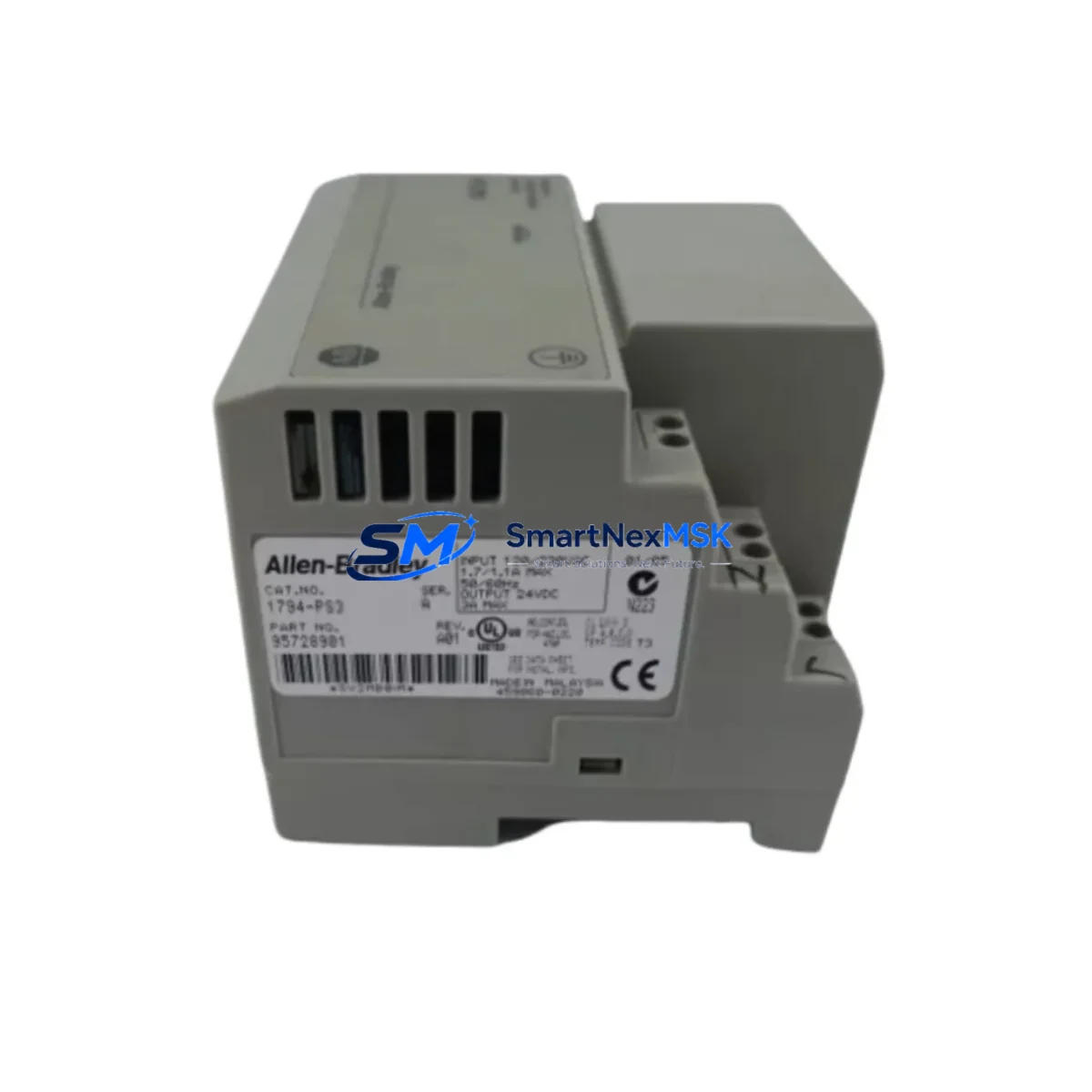
Allen-Bradley 1794-PS3 Maintenance-Ready Spare FLEX I/O
The Allen-Bradley 1794-PS3 is a 24VDC backplane power supply module designed for the FLEX I/O distributed I/O platform. In industrial maintenance environments, unplanned downtime caused by a failed power supply module can cascade across an entire I/O rack, halting production lines and triggering costly emergency shutdowns. Stocking a verified original 1794-PS3 spare is a fundamental element of any proactive maintenance strategy for facilities running Allen-Bradley FLEX I/O systems.
This unit supplies regulated backplane power to FLEX I/O adapter and I/O modules mounted on the 1794-TB3 or 1794-TB3S terminal base assemblies. It is engineered to operate reliably in demanding industrial environments, including those with high ambient temperatures, vibration, and electrical noise common in manufacturing, oil & gas, water treatment, and automotive assembly applications. Each unit shipped by SMARTNEXMSK is sourced from authorized supply chains, individually tested prior to dispatch, and covered by a 12-month warranty.
For maintenance engineers managing aging FLEX I/O installations, the 1794-PS3 is a direct replacement for earlier revisions of the same model. No firmware reconfiguration or adapter reprogramming is required when swapping a like-for-like unit. This makes it an ideal candidate for emergency replacement kits stored in the control room or maintenance workshop.
Spare Maintenance Table
| Parameter | Specification |
|---|---|
| Part Number / SKU | 1794-PS3 |
| Brand | Allen-Bradley (Rockwell Automation) |
| Series | FLEX I/O |
| Function | 24VDC Backplane Power Supply Module |
| Input Voltage | 18–31.2 VDC |
| Output (Backplane) | 5 VDC regulated backplane power |
| Compatible Adapters | 1794-AENT, 1794-ACN15, 1794-ADNK, 1794-APB |
| Compatible Terminal Bases | 1794-TB3, 1794-TB3S, 1794-TB32 |
| Installation | DIN rail or panel mount via FLEX I/O rack |
| Operating Temperature | 0°C to 55°C (32°F to 131°F) |
| Enclosure Rating | Open type — requires enclosure (IP20 equivalent) |
| Origin | USA (Rockwell Automation) |
| Condition | Original, new or refurbished-to-spec |
| Pre-shipment Testing | Yes — functional and electrical verification |
| Warranty | 12 Months |
| Maintenance Recommendation | Inspect every 12 months; replace at first sign of output instability or thermal stress |
Maintenance Planning for Continuous Operation
When a 1794-PS3 failure is suspected or confirmed, a thorough site inspection should extend beyond the power supply itself. Maintenance engineers should simultaneously evaluate the following components within the same control cabinet and I/O network:
Begin with the 1794-AENT EtherNet/IP adapter or the 1794-ACN15 ControlNet adapter — these communication modules share the backplane power rail and may exhibit erratic behavior or communication faults if the power supply has been operating in a degraded state. Check the adapter’s diagnostic LEDs and verify network connectivity before and after replacement.
Inspect the 1794-OB16 digital output module and 1794-IB16 digital input module for any latched fault states that may have been triggered by the power interruption. These I/O modules should be cycled and re-initialized after the power supply is replaced to ensure clean I/O mapping in the ControlLogix or CompactLogix PLC program.
Check the 24VDC field power supply feeding the 1794-PS3 input — a failing external power supply (such as an Allen-Bradley 1606-XLP or equivalent) can cause repeated 1794-PS3 failures if the root cause is not addressed. Measure input voltage under load to confirm it remains within the 18–31.2 VDC operating range.
Examine the 1794-TB3 terminal base for signs of overheating, discoloration, or loose field wiring. Terminal bases are often overlooked during spare part replacement but can cause intermittent faults if connector contacts are oxidized or mechanically stressed.
For systems using 1794-APB PROFIBUS-DP adapters, verify that the PROFIBUS network remains in a healthy state after power restoration. A power cycle on the I/O rack may cause the PROFIBUS master to flag the node as offline, requiring a manual re-scan or GSD re-initialization.
Additionally, inspect any signal isolators or intrinsic safety barriers connected to analog I/O modules such as the 1794-IE8 or 1794-OE4. These modules are sensitive to power quality and may require recalibration after a power supply replacement event. Fuse holders and DIN rail-mounted fuse terminals (such as Phoenix Contact or Weidmuller types) in the same cabinet should also be checked for continuity.
Finally, if the control system includes an HMI panel (such as a PanelView Plus 7 or PanelView 800) communicating with the same ControlLogix rack, verify that all tag subscriptions and alarm states have been restored correctly after the I/O rack comes back online.
Site Replacement Workflow
Step 1 — Isolate and de-energize: Follow your site’s lockout/tagout (LOTO) procedure. Disconnect the 24VDC field power feed to the 1794-PS3 before removing the module from the terminal base.
Step 2 — Document current configuration: Before removal, photograph the wiring layout on the 1794-TB3 terminal base and note the DIP switch or jumper settings on adjacent I/O modules. This prevents configuration errors during reinstallation.
Step 3 — Remove and inspect: Slide the 1794-PS3 off the terminal base. Inspect the terminal base connector for damage, corrosion, or debris. Clean if necessary before installing the replacement unit.
Step 4 — Install replacement 1794-PS3: Seat the new module firmly onto the 1794-TB3 terminal base. Reconnect the 24VDC input wiring. Verify torque on all field terminals per the installation manual (typically 0.5–0.8 Nm).
Step 5 — Power-up and verify: Restore field power and observe the module status LED. A solid green LED indicates normal operation. Check the adapter module (1794-AENT or equivalent) for successful network re-establishment. Verify I/O data in the PLC program via RSLogix 5000 or Studio 5000 online monitoring.
Step 6 — Update maintenance records: Log the replacement date, module serial number, and any observations in your CMMS or maintenance logbook. Schedule the next inspection interval (recommended: 12 months or per site maintenance schedule).
Spare Parts Support FAQ
Q1: Is the 1794-PS3 compatible with all FLEX I/O terminal bases?
The 1794-PS3 is designed for use with the 1794-TB3, 1794-TB3S, and 1794-TB32 terminal bases. It is not compatible with the 1794-TB2 or 1794-TBN series. Always verify the terminal base catalog number before ordering to ensure mechanical and electrical compatibility.
Q2: What is the recommended spare parts inventory strategy for FLEX I/O systems?
For critical production lines, we recommend maintaining at least one 1794-PS3 per FLEX I/O rack in your on-site spare parts inventory. For facilities with multiple FLEX I/O nodes, a centralized spare pool of 2–3 units is advisable. Long lead times for legacy automation components make proactive stocking essential for minimizing unplanned downtime.
Q3: How is each unit tested before shipment?
Every 1794-PS3 supplied by SMARTNEXMSK undergoes functional electrical testing prior to dispatch. This includes input voltage range verification, output voltage stability measurement under simulated backplane load, and visual inspection for physical damage. A test report is available upon request for quality-critical applications.
Q4: What does the 12-month warranty cover?
The 12-month warranty covers manufacturing defects and functional failures under normal operating conditions. It does not cover damage caused by incorrect installation, overvoltage events, or physical mishandling. In the event of a warranty claim, SMARTNEXMSK will provide a replacement unit or full refund after fault verification. Contact our technical team at [email protected] to initiate a warranty claim.
© 2026 SMARTNEXMSK. All rights reserved.
Original Source: https://smartnexmsk.com
Contact: [email protected] | +86 18259474341



