
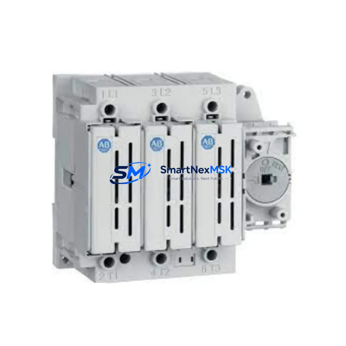
Allen-Bradley 194R-J400-1753 Retrofit-Ready Fusible Disconnect for 194R TSC Control Systems
The Allen-Bradley 194R-J400-1753 is a 30A, 600V fusible disconnect switch engineered for seamless integration into existing 194R TSC Series motor control and power distribution panels. As legacy control cabinets age and OEM support for discontinued models diminishes, the 194R-J400-1753 has become a critical retrofit component for engineers tasked with modernizing motor branch circuits, MCC buckets, and standalone control enclosures without triggering a full panel redesign.
This unit is fully compatible with the 194R TSC Series mounting rail and terminal block architecture, allowing direct substitution of end-of-life 194R-J400 variants without modification to existing DIN rail layouts or busbar configurations. The compact footprint and standardized terminal pitch make it suitable for high-density panel builds where space constraints limit the use of larger replacement alternatives.
Upgrade Compatibility Table
| Parameter | 194R-J400-1753 (This Unit) | Typical Legacy Replacement Target |
|---|---|---|
| Rated Current | 30A | 30A (194R-J400 variants) |
| Rated Voltage | 600V AC/DC | 600V AC/DC |
| Mounting | DIN Rail / Panel Mount | DIN Rail / Panel Mount |
| Fuse Class | Class J / Class CC compatible | Class J / Class CC |
| Terminal Type | Screw clamp, standard pitch | Screw clamp |
| Communication Compatibility | Passive (no bus interface) | Passive |
| Series Compatibility | 194R TSC Series | 194R TSC Series |
| Installation Requirement | No panel modification required | Direct drop-in |
| Retrofit Recommendation | Direct replacement; verify fuse sizing | Match load current and fuse class |
| Commissioning Note | Confirm torque spec on terminals | Per OEM wiring diagram |
| Warranty | 12 Months | — |
Retrofit Planning for Existing Automation Systems
When planning a retrofit around the 194R-J400-1753, engineers must account for the full scope of the branch circuit and motor control architecture. In a typical 194R TSC Series panel, the disconnect switch interfaces directly with the upstream power feed and downstream motor starter or variable frequency drive. Before removal of the legacy unit, verify that the incoming line voltage, phase configuration, and load current are within the 30A rating of the replacement module.
Terminal wiring should be documented prior to disconnection. The 194R-J400-1753 uses a standard screw-clamp terminal block compatible with the existing conductor gauges typically found in 194R TSC installations. If the panel also includes a 194L-E30-1753 or similar 194L Series load switch, confirm that the upstream fuse coordination remains intact after substitution.
In panels where the 194R-J400-1753 is installed alongside a PowerFlex 40 or PowerFlex 400 variable frequency drive, the disconnect must be positioned to allow safe isolation of the drive input without interrupting adjacent circuits. The 1492-SP Series supplementary protectors commonly used in the same enclosure should be reviewed for coordination with the new fuse class selected for the 194R-J400-1753.
For systems using a 1756-L71 or 1756-L73 ControlLogix controller as the supervisory PLC, the disconnect switch itself requires no program modification — however, if a 1794-IB16 FLEX I/O input module is monitoring the auxiliary contact of the legacy disconnect, the wiring to that input point must be verified against the new unit’s auxiliary contact terminal assignment. Similarly, if a 1769-L30ER CompactLogix controller is managing the motor branch via a 1769-OB16 digital output module, the enable/disable logic referencing the disconnect status bit should be tested in simulation before live commissioning.
Panels incorporating a 2711P-T10C4D8 PanelView Plus 6 HMI with a disconnect status indicator screen should have the associated HMI tag verified against the updated I/O mapping. If the legacy disconnect’s auxiliary contact was wired to a different input address than the replacement unit’s, the HMI graphic and alarm tag must be updated accordingly to avoid false status indications during operation.
Where the control cabinet uses a 1783-US8T Stratix 2000 unmanaged switch for device-level Ethernet connectivity, no changes to the network topology are required for this disconnect replacement. However, if the panel includes a 1734-AENT POINT I/O EtherNet/IP adapter managing distributed I/O across the same cabinet, the adapter’s configuration should be backed up before any wiring work begins to protect against accidental parameter loss during power cycling.
Downtime Control During System Migration
Minimizing unplanned downtime during a disconnect switch retrofit requires a structured pre-outage preparation process. Before the scheduled maintenance window, obtain a full backup of the PLC program from the 1756-L71 or equivalent controller using Studio 5000 Logix Designer. Export the HMI project from the PanelView terminal and store it on a secure engineering workstation. Photograph all existing terminal wiring on the legacy 194R-J400 unit before disconnection, and label each conductor with its destination terminal number.
During the outage, de-energize the panel at the upstream main disconnect and verify absence of voltage with a calibrated meter before touching any terminals. Remove the legacy disconnect, install the 194R-J400-1753, and re-terminate all conductors per the documented wiring layout. Torque all terminals to the manufacturer’s specification — under-torqued connections are a leading cause of thermal failures in retrofit installations.
After re-energization, perform a functional test of the disconnect’s open and close operation before restoring load. Verify that the auxiliary contact signal is correctly received at the PLC input module and that the HMI status indicator reflects the correct state. If the system uses a 1769-L30ER CompactLogix with online monitoring enabled, use the controller’s I/O tree to confirm the input bit toggles correctly with the physical disconnect position. Document the completed retrofit in the panel’s maintenance log and update the as-built wiring diagram to reflect the new component reference.
With proper pre-outage preparation, a single-disconnect retrofit of this type can typically be completed within a two-to-four hour maintenance window, preserving the original program logic, HMI screens, and communication links without modification.
Retrofit Support FAQ
Q: Is the 194R-J400-1753 a direct drop-in replacement for the original 194R-J400 in a 194R TSC Series panel?
A: Yes. The 194R-J400-1753 is dimensionally and electrically compatible with the 194R-J400 footprint used in 194R TSC Series installations. No panel modification or DIN rail adjustment is required for standard installations. Verify fuse class and conductor gauge before installation.
Q: What fuse class should be used with the 194R-J400-1753 during a retrofit?
A: The 194R-J400-1753 accepts Class J and Class CC fuses. Select the fuse based on the load current of the downstream motor or drive, maintaining coordination with any upstream 1492-SP Series supplementary protectors or branch circuit breakers in the same panel.
Q: How is the auxiliary contact wiring verified after replacement?
A: After installation, use the PLC’s online I/O monitoring (e.g., Studio 5000 Logix Designer connected to a 1756-L71 or 1769-L30ER) to confirm the auxiliary contact input bit toggles correctly when the disconnect is opened and closed. Cross-reference the HMI status tag on the PanelView terminal to ensure the display reflects the correct state.
Q: What warranty and pre-shipment testing does this unit include?
A: Every 194R-J400-1753 unit shipped by SMARTNEXMSK is covered by a 12-month warranty from the date of delivery. Units undergo pre-shipment functional testing including continuity verification, insulation resistance check, and mechanical operation inspection before dispatch. Expedited shipping is available for urgent retrofit and line-down situations.
© 2026 SMARTNEXMSK. All rights reserved.
Original Source: https://smartnexmsk.com
Contact: [email protected] | +86 18259474341



