
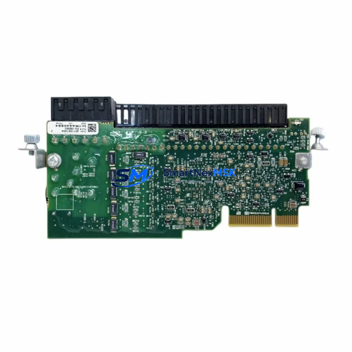
Allen-Bradley 20-750-S Maintenance-Ready Spare for PowerFlex 750 Automation
The Allen-Bradley 20-750-S Safe Torque Off (STO) Option Module is a critical safety component for PowerFlex 750 Series variable frequency drives deployed across industrial automation systems. When this module fails or reaches end-of-life, the entire drive — and potentially the production line — must be taken offline until a verified replacement is sourced and installed. Maintaining a ready spare of the 20-750-S in your parts inventory is one of the most effective strategies for minimizing unplanned downtime in safety-critical motion control applications.
Designed to meet IEC 61508 SIL 2 and EN ISO 13849-1 PLd safety standards, the 20-750-S integrates directly into the PowerFlex 755 and PowerFlex 753 drive option card slots. It provides dual-channel Safe Torque Off functionality, enabling the drive to safely remove torque from the motor without removing power from the drive itself — a key requirement in machinery safety circuits, emergency stop systems, and guard-interlocked automation cells. This original spare is sourced, inspected, and shipped with full functional verification and a 12-month warranty.
Spare Maintenance Table
| Parameter | Specification |
|---|---|
| Part Number | 20-750-S |
| Brand | Allen-Bradley (Rockwell Automation) |
| Compatible Series | PowerFlex 750 (753 / 755) |
| Function | Safe Torque Off (STO) Option Module |
| Safety Rating | SIL 2 (IEC 61508), PLd (EN ISO 13849-1) |
| Installation Slot | PowerFlex 750 Option Card Slot (Port 4 or 5) |
| Input Voltage | 24 VDC (from drive control power) |
| Response Time | ≤ 10 ms (STO activation) |
| Operating Temperature | 0°C to +50°C |
| Origin | United States |
| Compatibility | Drop-in replacement for existing 20-750-S installations |
| Maintenance Recommendation | Inspect wiring harness and STO input terminals at each planned shutdown |
| Warranty | 12 Months — tested and verified before shipment |
Maintenance Planning for Continuous Operation
When a PowerFlex 750 drive trips on a safety fault or the 20-750-S module is flagged during a routine control cabinet inspection, the replacement workflow extends beyond the module itself. Maintenance engineers should treat this event as an opportunity to audit the full safety and power circuit around the drive.
Begin by verifying the 24 VDC control power supply feeding the STO input terminals — a degraded or undersized power supply such as the 1606-XLP or 1606-XLS series can cause intermittent STO faults that mimic module failure. Check the STO wiring harness for insulation breakdown, loose ferrules, or terminal block corrosion on the 1492-J series terminal strips commonly used in PowerFlex 750 control panels.
Inspect the safety relay or safety controller driving the STO input — devices such as the MSR127RP or the GuardLogix 5570 safety controller output cards are frequently implicated in nuisance STO trips when their output contacts begin to wear. If the system uses a 440C-CR30 Configurable Safety Relay, verify the STO channel mapping and response time configuration has not drifted from the validated safety function parameters.
For drives with encoder feedback, check the 20-750-ENC-1 encoder option module for connector seating and signal integrity — a loose encoder connection can cause the drive to fault in a way that appears as an STO event. Similarly, inspect the 20-750-DNET-1 or 20-750-PNET-1 communication option modules for firmware version compatibility if the drive has recently undergone a control system upgrade.
In multi-drive panels, review the shared 24 VDC bus loading across all STO circuits. Overloaded control power buses are a common root cause of simultaneous STO faults across multiple PowerFlex 750 drives. Adding a dedicated 1606-XLP72E power supply for the STO circuit is a low-cost reliability improvement that maintenance teams often overlook.
Finally, document the replacement in your CMMS with the new module serial number, installation date, and post-replacement STO function test results. This record supports both safety audit compliance and future predictive maintenance scheduling.
Site Replacement Workflow
Replacing the 20-750-S in the field is a straightforward procedure when the correct spare is on hand. Begin by placing the drive in a safe, de-energized state — confirm STO is active and the motor has reached zero speed before opening the control cabinet. Remove the option card slot cover and extract the existing 20-750-S module by releasing the retention latch. Inspect the card slot connector for bent pins or contamination before inserting the replacement module.
After seating the new 20-750-S, restore control power and perform a full STO function test per the drive’s safety validation procedure before returning the machine to production. Verify that the drive firmware version is compatible with the replacement module — PowerFlex 755 drives running firmware below v7.001 may require a firmware update to correctly recognize the 20-750-S after replacement. This drop-in replacement maintains full system compatibility and does not require re-parameterization of the drive’s safety function settings in most standard installations.
For aging PowerFlex 750 systems where the drive frame itself is approaching end-of-support, stocking the 20-750-S alongside other high-wear option modules — including communication cards, encoder modules, and I/O option cards — is a proven strategy for extending system life by 3–5 years without a full drive replacement capital project.
Spare Parts Support FAQ
Q: Is this 20-750-S module compatible with both PowerFlex 753 and PowerFlex 755 drives?
A: Yes. The 20-750-S is designed for the PowerFlex 750 Series platform and is compatible with both the PowerFlex 753 and PowerFlex 755 drive families. Always confirm the drive firmware version meets the minimum requirement specified in Rockwell publication 750-UM001 before installation.
Q: How is the module tested before shipment?
A: Each 20-750-S unit undergoes functional verification including STO input response testing, visual inspection of the card edge connector, and continuity checks on all signal paths. Units are shipped with a test report and are covered by a 12-month warranty from the date of delivery.
Q: What is the recommended spare parts stocking strategy for PowerFlex 750 installations?
A: For facilities operating three or more PowerFlex 750 drives, we recommend maintaining at least one 20-750-S on the shelf alongside a spare 20-750-ENC-1 encoder module and a backup communication option card matching your network type. This covers the three most common option card failure modes and supports a same-shift recovery from most drive faults.
Q: Can this module replace an older revision of the 20-750-S?
A: In the vast majority of installations, yes. The 20-750-S has maintained backward hardware compatibility across revisions. If your system uses a safety validation report tied to a specific hardware revision, consult your safety engineer before substituting revisions in a validated safety function.
© 2026 SMARTNEXMSK. All rights reserved.
Original Source: https://smartnexmsk.com
Contact: [email protected] | +86 18259474341



