
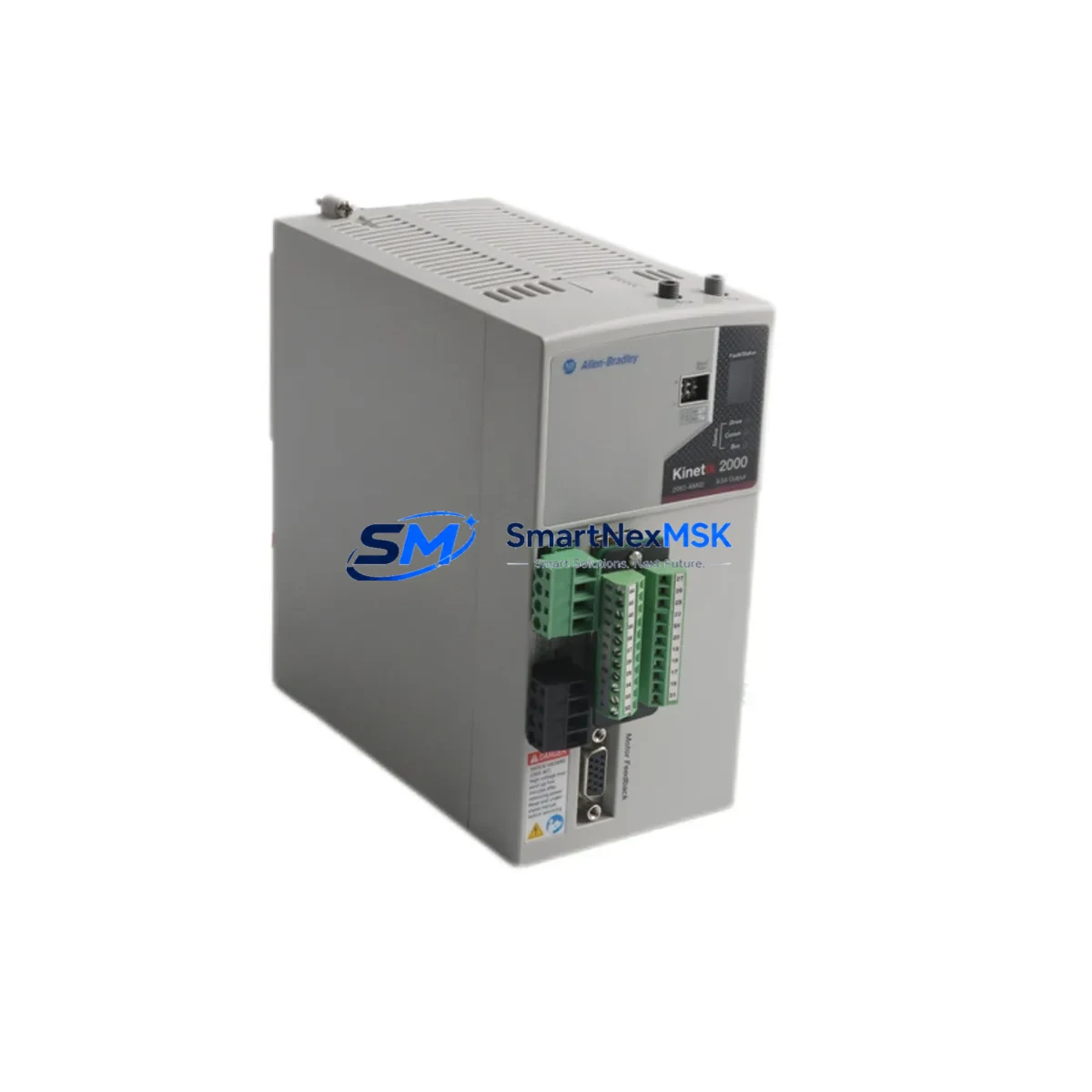
Allen-Bradley 2093-AM02 Spare for Kinetix 2000 Automation: Minimizing Downtime in Motion Control Systems
The Allen-Bradley 2093-AM02 is a dual-axis power module designed for the Kinetix 2000 multi-axis servo drive system, one of Rockwell Automation’s most widely deployed motion control platforms in discrete manufacturing, packaging, and material handling environments. As a maintenance-ready original spare, the 2093-AM02 enables maintenance engineers to execute rapid in-cabinet replacements without reconfiguration delays, preserving system uptime and protecting production schedules from unplanned servo axis failures.
For facilities running Kinetix 2000 multi-axis configurations, the 2093-AM02 power module is a critical inventory item. Its role in supplying DC bus power to paired inverter modules means that a single module failure can cascade into a full axis shutdown — or worse, a complete drive system trip. Stocking a verified original spare eliminates the lead-time risk associated with sourcing this module reactively during an emergency stoppage.
Every 2093-AM02 unit shipped by SMARTNEXMSK undergoes pre-shipment functional verification and is backed by a 12-month warranty, giving procurement engineers confidence in both quality and long-term supply continuity.
Spare Maintenance Table
| Parameter | Specification |
|---|---|
| SKU / Part Number | 2093-AM02 |
| Brand | Allen-Bradley (Rockwell Automation) |
| Series | Kinetix 2000 Multi-Axis Servo Drive |
| Module Type | Dual-Axis Power Module |
| Input Voltage | 195–264 VAC, 3-Phase, 50/60 Hz |
| DC Bus Output | Shared DC bus for paired inverter modules |
| Compatible Inverter Modules | 2093-AMP1, 2093-AMP2 (single/dual-axis inverters) |
| Compatible IAM | 2093-AC05-MP1, 2093-AC05-MP2 (Integrated Axis Modules) |
| Mounting | DIN rail / panel mount, shared bus bar connection |
| Operating Temperature | 0°C to 50°C (32°F to 122°F) |
| Protection Rating | IP20 (control cabinet installation) |
| Weight | Approx. 1,040 g |
| Origin | USA (Allen-Bradley / Rockwell Automation) |
| Compatibility | Drop-in replacement for existing 2093-AM02 installations |
| Maintenance Recommendation | Inspect DC bus connectors, bus bar torque, and cooling airflow at each planned maintenance interval |
| Warranty | 12 Months — covers functional defects under normal operating conditions |
Maintenance Planning for Continuous Operation
When replacing the 2093-AM02 power module during a planned or emergency maintenance event, a thorough inspection of the surrounding drive system components is essential to prevent repeat failures and ensure full system restoration. Maintenance engineers should treat the module swap as an opportunity for a broader Kinetix 2000 cabinet audit.
Begin by verifying the 2093-AC05-MP1 or 2093-AC05-MP2 Integrated Axis Module (IAM) — the IAM governs converter and inverter functions for the first axis and is the logical starting point for any DC bus fault investigation. Check the IAM’s status LEDs, fault codes via RSLogix 5000 or Studio 5000, and inspect its input power wiring for signs of thermal stress or loose terminations.
Next, inspect the 2093-AMP1 and 2093-AMP2 inverter modules sharing the DC bus with the 2093-AM02. A failed power module can subject adjacent inverters to voltage transients; verify that each inverter’s gate drive circuitry is intact and that no fault codes are latched. While the cabinet is open, check the shared DC bus bar connections and torque all bus bar fasteners to specification — loose bus connections are a leading cause of intermittent axis faults in multi-axis Kinetix systems.
Inspect the 2090-series feedback cables (such as the 2090-XXNFMF-Sxx motor feedback cables) connecting servo motors to their respective inverter modules. Damaged or improperly routed feedback cables can cause encoder signal errors that mimic power module faults. Similarly, review the 2090-CPWM7DF-16AAxx power cables for insulation integrity and connector seating.
For the control-side infrastructure, verify the 1756-M02AE or 1756-M08SE motion control module in the ControlLogix or CompactLogix backplane — confirm that axis configuration parameters remain intact after the module replacement and that the SERCOS or EtherNet/IP motion network is communicating correctly. If the system uses a 1756-EN2T or 1756-EN2TR EtherNet/IP communication module, check for any network faults that may have been triggered by the drive fault event.
Do not overlook the 1492-series terminal blocks and wiring duct within the control cabinet. Thermal cycling from repeated fault events can loosen terminal screws and degrade wire insulation at termination points. A torque check of all I/O and power terminals is a low-cost step that prevents future nuisance faults.
Finally, confirm that the 24 VDC control power supply feeding the Kinetix 2000 system’s logic circuits is within specification. An under-voltage condition on the 24 VDC rail is a common root cause of unexplained drive faults and should be measured under load before the system is returned to production.
Site Replacement Workflow
Step 1 — Fault Isolation: Use Studio 5000 or RSLogix 5000 to capture the active fault code on the affected axis. Document the fault history before clearing any codes. This data is critical for root cause analysis and for confirming that the 2093-AM02 is the correct replacement target.
Step 2 — Safe De-energization: Follow LOTO (Lockout/Tagout) procedures. Discharge the DC bus capacitors fully before touching any bus bar connections — the Kinetix 2000 system requires a minimum 5-minute discharge wait after AC power removal. Verify bus voltage with a calibrated meter before proceeding.
Step 3 — Module Removal: Disconnect the AC input power wiring, DC bus bar connections, and any control signal connectors from the 2093-AM02. Note the torque values and wire routing for reinstallation reference. Remove the module from the DIN rail or panel mount.
Step 4 — Replacement Installation: Install the new 2093-AM02 in the same position. Reconnect all wiring in reverse order, torquing bus bar fasteners to the manufacturer’s specification. Verify that the module catalog number matches the original — the 2093-AM02 is not interchangeable with single-axis power modules without a full system reconfiguration.
Step 5 — Power-Up and Verification: Restore AC power and monitor the IAM and all axis modules for fault-free startup. Use Studio 5000 to confirm that all axes are in the “Ready” state and that no new fault codes are present. Run a low-speed jog test on each axis before returning the machine to automatic mode.
Step 6 — Documentation: Record the replacement in the equipment maintenance log, including the date, replaced part number, fault history, and post-replacement test results. Update the site spare parts inventory to trigger reorder of a replacement 2093-AM02 unit.
Spare Parts Support FAQ
Q1: Is the 2093-AM02 still available as a new original spare, or is it only available as refurbished?
SMARTNEXMSK supplies the 2093-AM02 as an original spare sourced from authorized distribution channels. Each unit is pre-shipment tested and ships with a 12-month warranty covering functional defects. We maintain stock specifically to support legacy Kinetix 2000 installations that cannot be immediately migrated to newer Kinetix 5500 or 5700 platforms.
Q2: How do I confirm compatibility before ordering?
The 2093-AM02 is compatible with Kinetix 2000 multi-axis drive systems using the shared DC bus architecture. Confirm your existing module’s catalog number label before ordering. If your system uses a different power rating or axis count configuration, contact [email protected] with your full drive system catalog numbers for a compatibility review prior to purchase.
Q3: What is the typical lead time and how is the unit tested before shipment?
In-stock units ship within 1–3 business days. Each 2093-AM02 undergoes a pre-shipment functional check covering DC bus integrity, connector condition, and visual inspection for physical damage. A test report is available upon request. Express shipping options are available for emergency downtime situations.
Q4: What is covered under the 12-month warranty?
The 12-month warranty covers functional defects arising under normal operating conditions — including DC bus failures, internal component faults, and connector integrity issues. It does not cover damage resulting from incorrect installation, overvoltage events, or physical mishandling. Warranty claims are processed directly through SMARTNEXMSK with a target response time of 48 hours.
© 2026 SMARTNEXMSK. All rights reserved.
Original Source: https://smartnexmsk.com
Contact: [email protected] | +86 18259474341



