
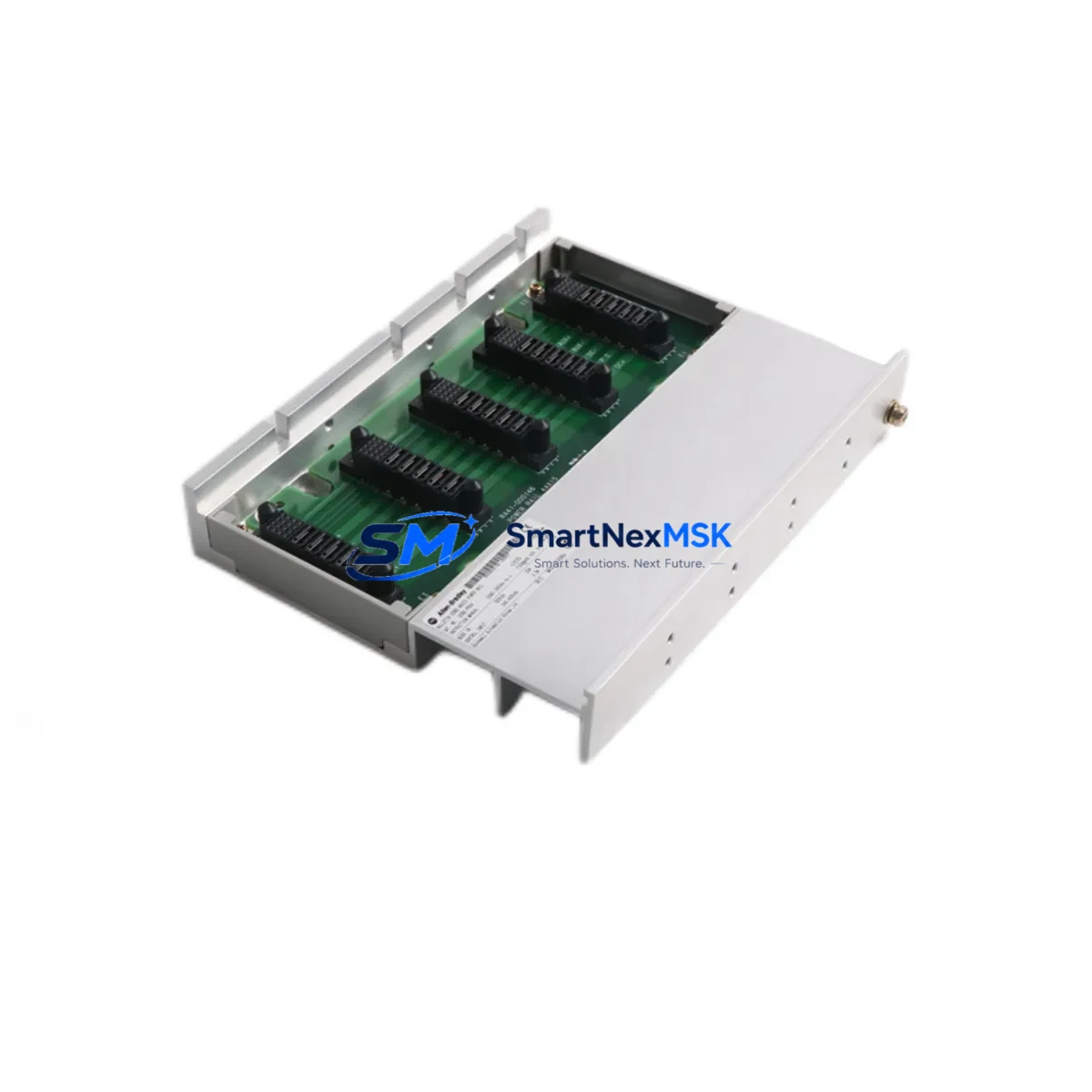
Allen-Bradley 2093-PRS4 Retrofit-Ready Power Rail for Kinetix 2000 Control Systems
The Allen-Bradley 2093-PRS4 is a 4-axis slim power rail designed for the Kinetix 2000 multi-axis servo drive system. As legacy Kinetix 2000 installations reach end-of-life or require capacity expansion, the 2093-PRS4 remains the critical backbone that physically and electrically integrates the inverter modules, power module, and control interface into a unified drive assembly. Whether you are replacing a failed rail in an existing cabinet or planning a phased modernization of a multi-axis motion control system, the 2093-PRS4 provides a direct, wiring-compatible solution that minimizes engineering rework and commissioning time.
At SMARTNEXMSK, we maintain verified stock of the 2093-PRS4 sourced from authorized distribution channels. Each unit undergoes pre-shipment functional inspection and ships with a 12-month warranty covering manufacturing defects and operational failures under normal service conditions. Global logistics support is available with lead times confirmed at order placement.
Upgrade Compatibility Table
| Parameter | Details |
|---|---|
| SKU / Catalog Number | 2093-PRS4 |
| Brand / Manufacturer | Allen-Bradley (Rockwell Automation) |
| Series | Kinetix 2000 |
| Axis Capacity | 4-Axis Slim Power Rail |
| Compatible Inverter Modules | 2093-AMP1, 2093-AMP2, 2093-AMP5 (Kinetix 2000 series) |
| Compatible Power Module | 2093-AC05-MP1, 2093-AC05-MP2 |
| Backplane Interface | Kinetix 2000 proprietary slim rail connector |
| Installation Requirement | DIN rail or panel mount; standard Kinetix 2000 cabinet footprint |
| Communication Compatibility | SERCOS interface via 2093-DNF or 2093-DNET DeviceNet option module |
| Replacement Recommendation | Direct drop-in for existing 2093-PRS4 installations; no firmware change required |
| Commissioning Notes | Verify module slot addressing in RSLogix 5000 / Studio 5000 after rail replacement |
| Warranty | 12 Months — covers manufacturing defects and operational failures |
Retrofit Planning for Existing Automation Systems
Replacing or upgrading the 2093-PRS4 in a live production environment requires careful pre-work to avoid extended downtime and configuration loss. Before removing the existing rail, engineers should document the physical slot positions of all installed inverter modules — typically 2093-AMP1 or 2093-AMP2 single-axis inverters — and confirm that the power module (such as the 2093-AC05-MP2) is de-energized and locked out per site LOTO procedures.
Terminal wiring on the power module side must be photographed and labeled before disconnection. The 2093-PRS4 rail itself carries no field-wiring terminals, but the associated power module and any installed 2093-DNF SERCOS fiber interface module or 2093-DNET DeviceNet communication adapter will require careful re-seating and torque verification after the new rail is installed. If the system uses a 2090-XXNFMF-Sxx SERCOS fiber cable set, inspect connectors for contamination before reconnection — fiber contamination is a common source of communication faults after mechanical disturbance.
For systems integrated with a CompactLogix L3x or ControlLogix L6x controller via a 1756-M02AE or 1756-M08SE motion module, the axis configuration stored in the Studio 5000 project file remains valid after a like-for-like 2093-PRS4 replacement. No axis re-tuning is required unless the inverter modules themselves are also being replaced. If the retrofit includes upgrading from 2093-AMP1 to 2093-AMP2 inverters to increase per-axis current capacity, axis parameters including torque limits, velocity feedforward, and position loop gains should be re-verified against the motor nameplate data for the connected MPL or MPM servo motors.
Panel layout should also account for the 24 VDC control power supply feeding the Kinetix 2000 system. A 1606-XLP or equivalent 24 VDC power supply must be confirmed to have sufficient current headroom after adding any additional I/O or communication modules to the cabinet. If the retrofit includes adding a 1734-AENT POINT I/O EtherNet/IP adapter or expanding the local I/O rack with 1734-IB8 digital input or 1734-OB8 digital output modules, recalculate the 24 VDC bus load before commissioning.
HMI screens built on PanelView Plus 6 or PanelView 800 terminals referencing Kinetix 2000 drive tags should be reviewed to confirm that axis tag names in the FactoryTalk View ME project match the Studio 5000 axis names after any controller program update. Mismatched tag references are a common source of HMI alarm display errors following a drive system retrofit.
Downtime Control During System Migration
Minimizing unplanned downtime during a 2093-PRS4 rail replacement begins with pre-staging. Before the maintenance window opens, the replacement rail and all associated modules should be physically verified against the existing configuration — slot count, inverter catalog numbers, and power module variant. A pre-configured spare assembly, with inverter modules pre-installed on the new rail and axis parameters pre-loaded via a laptop running Studio 5000, can reduce in-cabinet swap time to under two hours for a 4-axis system.
Back up the existing controller program from the CompactLogix or ControlLogix processor to both a local project file and a removable storage device before beginning any mechanical work. If the system uses a 1756-ENBT or 1756-EN2T EtherNet/IP communication module for supervisory SCADA connectivity, note the IP address configuration and confirm that the replacement does not alter the controller’s network identity.
After mechanical installation and wiring reconnection, power the system in a controlled sequence: control power first, then bus power. Monitor the drive status indicators on each 2093-AMP inverter module and confirm that the SERCOS ring initializes correctly — a solid green ring light on the 2093-DNF module indicates successful fiber ring closure. Run a manual jog test on each axis at reduced speed before releasing the system to automatic mode. Document the commissioning test results and retain them with the site maintenance record to support the 12-month warranty claim process if required.
For facilities operating continuous processes where even a brief stop is costly, consider a parallel-build strategy: construct and test the new Kinetix 2000 assembly on a bench panel, validate all axis motion profiles against the production program offline, then execute the physical swap during a scheduled micro-shutdown. This approach has been used successfully in food processing, packaging, and automotive assembly applications where the Kinetix 2000 platform remains in active service.
Retrofit Support FAQ
Q1: Is the 2093-PRS4 a direct replacement for an existing Kinetix 2000 power rail, or does it require firmware or software changes?
The 2093-PRS4 is a direct mechanical and electrical replacement for an existing Kinetix 2000 4-axis slim power rail. No firmware changes are required on the inverter modules or the controller. The Studio 5000 axis configuration remains valid for a like-for-like rail swap. If inverter modules are also being upgraded, axis parameter verification is recommended.
Q2: What wiring checks are required before installing the replacement rail?
Confirm that all power module input wiring (AC line, PE ground) and 24 VDC control power connections are correctly re-terminated to the original torque specifications after installation. The 2093-PRS4 rail itself has no field terminals, but the associated power module and communication option modules must be fully re-seated and secured. Verify SERCOS fiber connector cleanliness if the system uses a fiber-based motion network.
Q3: How is module slot addressing verified after rail replacement?
After installing the new 2093-PRS4 and re-seating all inverter modules in their original slot positions, go online with the controller in Studio 5000 and verify that each axis object maps correctly to its physical drive slot. If any axis shows a fault or offline status, check the module slot number in the axis properties and confirm it matches the physical installation. A SERCOS ring re-initialization (power cycle of the drive system) is typically sufficient to restore communication.
Q4: What does the 12-month warranty cover, and how is a claim initiated?
The 12-month warranty covers manufacturing defects and operational failures under normal industrial service conditions. It does not cover damage resulting from incorrect installation, overvoltage events, or physical impact. To initiate a warranty claim, contact SMARTNEXMSK at [email protected] with the order reference number, a description of the fault symptom, and any available fault codes from the drive or controller. Replacement or repair will be coordinated within the warranty period without additional parts cost.
© 2026 SMARTNEXMSK. All rights reserved.
Original Source: https://smartnexmsk.com
Contact: [email protected] | +86 18259474341



