
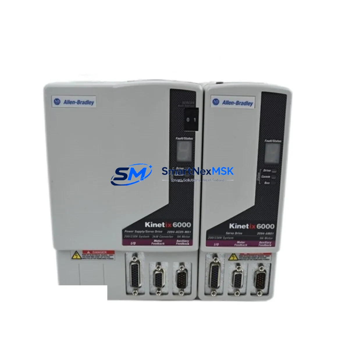
Allen-Bradley 2094-AM01 Retrofit-Ready Axis Module for Kinetix 6000 Control Systems
The Allen-Bradley 2094-AM01 is a high-performance servo drive axis module designed for the Kinetix 6000 multi-axis servo drive platform. As legacy motion control systems reach end-of-life or face discontinued spare parts availability, the 2094-AM01 has become a critical retrofit component for engineers tasked with modernizing existing servo infrastructure without full system replacement. Whether you are recovering a production line from an unexpected axis failure, executing a planned upgrade from an older Kinetix 2000 platform, or expanding axis count on an existing Kinetix 6000 rack, the 2094-AM01 delivers the electrical and mechanical compatibility required for a smooth, low-risk transition.
In retrofit and replacement scenarios, the 2094-AM01 slots directly into the 2094 series power rail, sharing the DC bus with the Kinetix 6000 integrated axis module (IAM) such as the 2094-BC01-MP5 or 2094-BC02-M02-S. This shared DC bus architecture means that during a single-axis swap, the remaining axes — including those driven by companion 2094-AM02 or 2094-AM03 modules — continue to operate without interruption, significantly reducing planned downtime windows. Engineers should verify that the existing 2094 series power rail has sufficient capacity for the replacement module’s continuous and peak current draw before installation.
Before committing to a 2094-AM01 replacement, the following compatibility checkpoints are essential. First, confirm the power rail catalog number and its rated bus current capacity against the total axis load. Second, inspect the feedback connector pinout: the 2094-AM01 accepts standard Kinetix 6000 feedback cables compatible with 2090-series motor feedback cables, including those used with MPL, MPM, and TLP series servo motors. Third, verify the axis module address assignment within the Logix Designer (Studio 5000) project — the axis number is determined by slot position on the power rail, and any change in physical slot must be reflected in the controller tag database and motion group configuration. Fourth, review the existing Logix 5000 or Studio 5000 program for any axis-specific tuning parameters (velocity loop gain, position error tolerance, acceleration/deceleration limits) that must be re-entered or re-tuned after module swap.
Communication between the Kinetix 6000 drive system and the host ControlLogix or CompactLogix controller is handled via the SERCOS fiber-optic ring, typically using a 1756-M08SE or 1756-M16SE SERCOS interface module. During a retrofit, it is critical to confirm that the SERCOS ring remains intact and that the node address of the replacement axis module is correctly set. If the retrofit involves migrating from an older SERCOS-based system to an EtherNet/IP motion architecture, a parallel migration path using a Kinetix 5700 or Kinetix 5500 platform may be considered, though the 2094-AM01 itself is native to the SERCOS-based Kinetix 6000 ecosystem.
For control cabinet integration, the 2094-AM01 mounts on the 2094 power rail alongside the IAM and other axis modules. The cabinet must provide adequate ventilation as specified in the Kinetix 6000 installation manual, with particular attention to ambient temperature limits and minimum clearance distances. If the retrofit involves replacing a failed module in an existing cabinet, inspect the power rail connector and bus bar for signs of arcing or contamination before installing the replacement unit. The 24 VDC control power supply — often sourced from a 1606-XLP or equivalent Allen-Bradley power supply — must be verified for adequate current capacity to support the control logic of all modules on the rail.
Commissioning a replacement 2094-AM01 follows the standard Kinetix 6000 startup procedure: configure the axis properties in Studio 5000, run the Hookup Diagnostics test to verify motor-to-drive wiring polarity and feedback signal integrity, then execute the Tune procedure to establish servo loop parameters. If the replaced axis is part of a coordinated motion group — for example, a gantry or electronic cam application — the entire motion group should be re-validated after the axis swap to confirm synchronized behavior. HMI screens built on FactoryTalk View or PanelView Plus terminals that display axis status, fault codes, or position feedback should also be tested to confirm that tag references remain valid after the module replacement.
Upgrade Compatibility Table
| Parameter | Details |
|---|---|
| Compatible Platform | Kinetix 6000 Multi-Axis Servo Drive System |
| Power Rail Compatibility | 2094 Series Power Rail (2094-PRS6, 2094-PRS16, etc.) |
| Communication Interface | SERCOS Fiber-Optic Ring (via 1756-M08SE / 1756-M16SE) |
| Feedback Cable Compatibility | 2090-Series Motor Feedback Cables (MPL, MPM, TLP Series Motors) |
| Controller Compatibility | ControlLogix (1756), CompactLogix (1769) with SERCOS Interface |
| Slot / Address Assignment | Determined by physical slot position on power rail; must match Studio 5000 axis tag |
| DC Bus Architecture | Shared DC Bus with IAM (e.g., 2094-BC01-MP5); no separate rectifier required |
| Installation Requirement | Adequate cabinet ventilation per Kinetix 6000 installation manual; 24 VDC control power |
| Commissioning Tool | Studio 5000 Logix Designer (v21 or later recommended) |
| Replacement Recommendation | Direct drop-in for same-slot 2094-AM01; verify rail capacity before installing |
| Debugging Focus | Hookup Diagnostics, Tune Procedure, Motion Group Re-validation |
| Warranty | 12-Month Warranty — covers manufacturing defects and functional failure under normal operating conditions |
Retrofit Planning for Existing Automation Systems
A successful 2094-AM01 retrofit begins well before the module arrives on-site. Start by auditing the existing Kinetix 6000 system: document the power rail catalog number, the IAM model (such as the 2094-BC01-MP5 or 2094-BC02-M02-S), and the catalog numbers of all axis modules currently installed. Identify the motor models connected to each axis — MPL-B430P, MPL-B540F, or similar — and cross-reference their continuous stall current against the axis module’s rated output current to confirm the 2094-AM01 is appropriately sized for the load.
Next, gather the 2090-series feedback cables and motor power cables. In many retrofit scenarios, existing cables can be reused if they are undamaged and correctly pinned for the Kinetix 6000 feedback interface. If the retrofit involves a motor replacement alongside the axis module swap, new 2090-CPBM7DF or 2090-CFBM7DF series cables may be required. Confirm that the 1756-M08SE or 1756-M16SE SERCOS interface module firmware is current and that the SERCOS ring optical budget is within specification — degraded fiber connections are a common source of commissioning delays in retrofit projects.
For control power, verify that the existing 24 VDC supply (often a 1606-XLP72E or 1606-XLP120E) has sufficient headroom to support the additional control logic load of the replacement module. If the retrofit also involves adding I/O — for example, integrating a 1756-IB16 digital input module or a 1756-OF8 analog output module for process feedback — recalculate the total backplane current budget for the ControlLogix chassis. Similarly, if the project includes upgrading the operator interface, a PanelView Plus 7 terminal with updated FactoryTalk View ME application screens should be pre-tested in a staging environment before deployment to the production floor.
Programming preparation is equally important. Export a backup of the existing Studio 5000 project before making any changes. If the retrofit involves migrating from Logix 5000 v16 or earlier, verify that all motion instructions (MAM, MAS, MAPC, MAAT) are compatible with the target firmware version. Coordinate motion applications — such as electronic gearing using the MAGE instruction or cam profiles using the MAPC instruction — require particular attention to ensure that axis relationships are preserved after the module swap. If the system includes a DeviceNet network for distributed I/O via a 1756-DNB scanner module, confirm that the network scan list remains intact and that no address conflicts are introduced by the retrofit.
Downtime Control During System Migration
Minimizing unplanned downtime is the primary operational concern in any Kinetix 6000 axis module replacement. The shared DC bus architecture of the 2094 series power rail is a significant advantage here: because the IAM provides rectification and bus regulation for all axis modules on the rail, a single-axis swap does not require powering down the entire drive system if the remaining axes can be safely inhibited during the swap window. Work with the machine builder or OEM documentation to identify which axes can be safely disabled without triggering a full system fault or safety circuit trip.
Before removing the failed or obsolete 2094-AM01, execute a controlled stop of all axes in the motion group using the MAS (Motion Axis Stop) instruction, then inhibit the axis in the Studio 5000 project to prevent the controller from attempting to command the absent module. After installing the replacement module, re-enable the axis, run Hookup Diagnostics, and complete the Tune procedure before returning the axis to automatic control. This sequence — inhibit, swap, re-enable, tune, validate — is the standard approach for containing the downtime window to the minimum necessary for safe module replacement and recommissioning.
For planned maintenance windows, pre-stage the replacement 2094-AM01 by verifying its firmware version and running a bench-level power-on test if possible. Having the Studio 5000 project open and the axis configuration pre-loaded on the engineering workstation before the maintenance window begins can reduce on-site commissioning time significantly. If the retrofit is part of a larger system upgrade that also involves replacing the 1756-L7x or 1756-L8x ControlLogix controller, coordinate the controller firmware upgrade and project download with the axis module swap to avoid multiple separate downtime events.
Retrofit Support FAQ
Q: Is the 2094-AM01 a direct replacement for a failed axis module in an existing Kinetix 6000 system?
A: Yes. The 2094-AM01 is a direct slot-compatible replacement for an existing 2094-AM01 in any 2094 series power rail. No mechanical or electrical modifications to the power rail are required. After installation, re-configure the axis in Studio 5000, run Hookup Diagnostics, and complete the Tune procedure to restore full operation.
Q: What wiring and feedback connections need to be verified during installation?
A: Verify the motor power cable (U, V, W phase connections and PE ground), the 2090-series feedback cable connector at both the drive and motor ends, and the 24 VDC control power connection on the power rail. Confirm that the SERCOS fiber-optic ring connections (TX and RX) are secure and that the optical signal level is within specification using the SERCOS interface module diagnostics in Studio 5000.
Q: How do I confirm compatibility with my existing motor and controller before ordering?
A: Provide the motor catalog number (e.g., MPL-B430P-MK22AA), the power rail catalog number, the IAM catalog number, and the Studio 5000 project firmware version. Cross-reference the motor’s continuous stall current against the 2094-AM01’s rated output current. Confirm that the SERCOS interface module (1756-M08SE or 1756-M16SE) supports the number of axes including the replacement module.
Q: What does the 12-month warranty cover, and what is the shipping and testing process?
A: Every 2094-AM01 unit is functionally tested prior to shipment to verify power-on operation and communication readiness. The 12-month warranty covers manufacturing defects and functional failure under normal operating conditions from the date of shipment. Units are packaged in anti-static, shock-protected packaging suitable for international freight. Expedited shipping options are available for urgent production recovery situations. Contact [email protected] or +86 18259474341 for lead time and logistics confirmation.
© 2026 SMARTNEXMSK. All rights reserved. Original Source: https://smartnexmsk.com | Contact: [email protected] | +86 18259474341



