
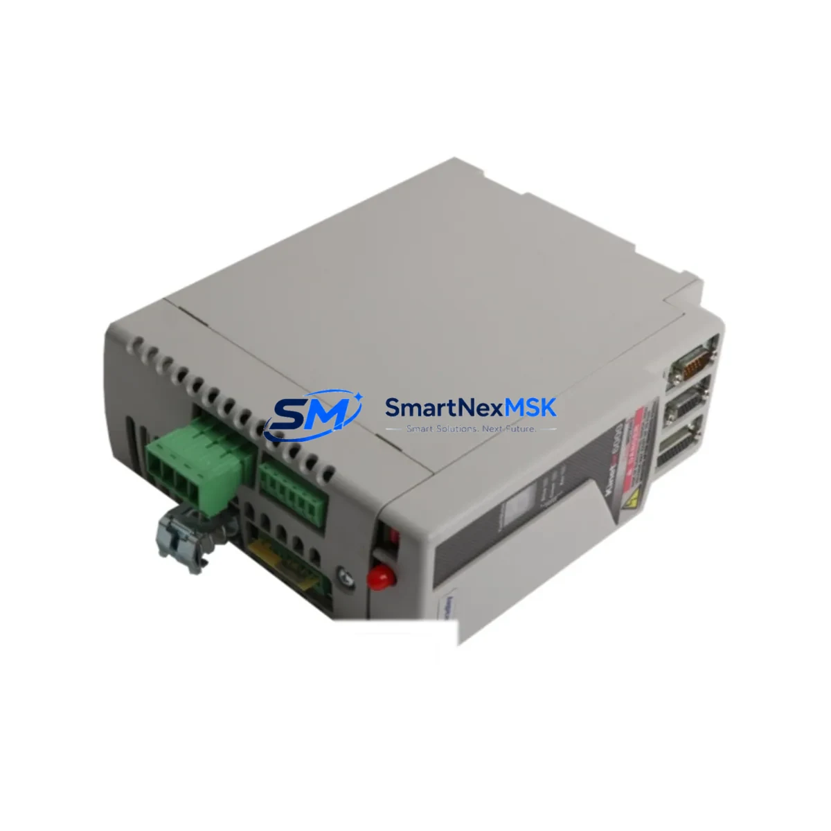
Allen-Bradley 2094-AM02-S Retrofit-Ready Servo Drive for Kinetix 6000 Control Systems
The Allen-Bradley 2094-AM02-S is a 2-axis shared DC bus power module designed for the Kinetix 6000 multi-axis servo drive platform. As legacy Kinetix 6000 systems approach end-of-life and spare parts become increasingly scarce, the 2094-AM02-S remains one of the most sought-after retrofit and replacement components for engineers managing aging servo motion control infrastructure. Whether you are restoring a failed axis, upgrading a multi-axis gantry system, or consolidating a control cabinet during a broader automation modernization project, this module provides a verified drop-in solution with full backward compatibility across the Kinetix 6000 drive family.
The 2094-AM02-S operates within the Kinetix 6000 integrated motion architecture, sharing a common DC bus with other axis modules such as the 2094-AM01 single-axis module and the 2094-AM03-S three-axis variant. It is designed to mount directly onto the 2094-XL75S-C1 or 2094-XL75S-C3 power rail, and integrates with the 2094-BC01-MP5-M Bulletin 2094 bus conditioner for multi-axis configurations. Engineers replacing a failed 2094-AM02-S should verify the existing power rail slot assignment, confirm the DC bus capacitor bank condition, and check that the 2094-PRS7 power rail spacer kit is correctly installed before inserting the replacement module.
Upgrade Compatibility Table
| Parameter | Details |
|---|---|
| Compatible Platform | Kinetix 6000 Multi-Axis Servo Drive System |
| Axes Supported | 2-Axis Shared DC Bus |
| Power Rail Compatibility | 2094-XL75S-C1, 2094-XL75S-C3 |
| Bus Conditioner | 2094-BC01-MP5-M |
| Communication Interface | SERCOS II (fiber optic ring) |
| Controller Compatibility | ControlLogix 1756-L6x, 1756-L7x series via 1756-M08SE SERCOS module |
| Installation Requirement | Slot-based power rail mounting; confirm slot address in RSLogix 5000 / Studio 5000 |
| Wiring Compatibility | Terminal block pinout identical to prior 2094-AM02 (non-S); no rewiring required |
| Replacement Recommendation | Direct drop-in for failed or end-of-life 2094-AM02-S units |
| Commissioning Note | Re-download axis configuration via Studio 5000 Logix Designer after module swap |
| Warranty | 12-Month Warranty included |
Retrofit Planning for Existing Automation Systems
Successful retrofit of the 2094-AM02-S into an existing Kinetix 6000 system requires a structured pre-installation review. Begin by auditing the control cabinet layout to confirm available power rail slots and verify that the 2094-SE02F-M00-S0 SERCOS fiber optic cables connecting the axis modules to the 1756-M08SE motion control card are undamaged and correctly routed. The SERCOS II ring topology is sensitive to fiber continuity; a single broken or dirty connector will prevent the entire ring from initializing.
Next, review the axis configuration stored in your Studio 5000 Logix Designer project file. The 2094-AM02-S occupies two axis slots on the power rail, and the slot address must match the axis number assigned in the motion group configuration. If the original module was replaced due to a fault rather than planned maintenance, retrieve the fault code history from the ControlLogix 1756-L71 or 1756-L73 controller using RSLinx Classic or FactoryTalk Diagnostics before powering the replacement module, to rule out upstream causes such as regenerative energy overload or DC bus overvoltage.
For systems that also include a 2094-EN02D-M01-S1 Kinetix 6000 Ethernet/IP drive or a 2094-AM01 single-axis module sharing the same bus, confirm that the total bus load does not exceed the capacity of the 2094-BC01-MP5-M bus conditioner. In multi-axis cabinets, the 2094-XL75S-C3 power rail supports up to three axis modules; exceeding this with an improperly sized bus conditioner is a common cause of nuisance faults during retrofit commissioning.
HMI screens built on PanelView Plus 7 or FactoryTalk View SE that display axis status, drive fault codes, and servo enable states should be validated after the module swap. If the axis tag names or module slot addresses changed during the retrofit, update the HMI display links accordingly to avoid misleading operator feedback during the first production run after restart.
All units supplied by SMARTNEXMSK are pre-tested prior to shipment. Each 2094-AM02-S undergoes functional verification including DC bus charge/discharge cycling, axis enable signal testing, and SERCOS ring initialization checks. Units are shipped with original-style packaging and include a 12-month warranty covering manufacturing defects and functional failures under normal operating conditions.
Downtime Control During System Migration
Minimizing unplanned downtime during a Kinetix 6000 servo drive replacement is achievable with disciplined pre-staging. Before the maintenance window opens, export the complete Studio 5000 project file from the ControlLogix controller and store a backup on a separate engineering workstation. Confirm that the 1756-ENBT or 1756-EN2T Ethernet/IP communication module is accessible for remote monitoring during the swap, so that the control system status can be observed without requiring physical presence at the panel.
During the swap, place the ControlLogix controller in Program mode to inhibit all motion commands. Remove the faulted 2094-AM02-S from the power rail only after confirming that the DC bus voltage has fully discharged — the bus capacitors in a Kinetix 6000 system can retain dangerous voltage levels for several minutes after power removal. Use the bus voltage indicator LED on the 2094-BC01-MP5-M bus conditioner as a discharge confirmation signal before touching any bus bar connections.
After installing the replacement module, restore power and allow the SERCOS ring to initialize. Download the axis configuration from Studio 5000 and perform a controlled jog test at reduced speed before returning the axis to automatic mode. For systems with safety functions enabled via a 1756-L7xS GuardLogix controller, verify that the safe torque-off (STO) and safe stop (SS1) functions respond correctly before releasing the machine to production. This structured approach typically allows a complete Kinetix 6000 axis module replacement to be completed within a two-to-four hour maintenance window, preserving the original program logic and HMI configuration without modification.
Retrofit Support FAQ
Q: Is the 2094-AM02-S a direct replacement for the original 2094-AM02?
A: Yes. The 2094-AM02-S is the current catalog number for the 2-axis Kinetix 6000 shared DC bus power module and is fully backward compatible with systems originally built around the 2094-AM02. No wiring changes or firmware updates are required for a direct swap.
Q: What commissioning steps are required after installing a replacement 2094-AM02-S?
A: After physical installation, place the ControlLogix controller in Program mode, download the existing axis configuration via Studio 5000 Logix Designer, and perform a controlled jog test to verify encoder feedback, torque response, and SERCOS communication integrity before returning to Run mode.
Q: How do I verify wiring compatibility before installation?
A: Compare the terminal block layout of the replacement module against the existing wiring diagram for your Kinetix 6000 cabinet. The 2094-AM02-S uses the same motor power (MP) and feedback (MF) connector pinout as previous revisions. Confirm motor cable shield grounding and verify that the 2090-series servo motor cables are correctly seated before energizing.
Q: What does the 12-month warranty cover?
A: The 12-month warranty covers manufacturing defects and functional failures under normal operating conditions from the date of shipment. Each unit is pre-tested prior to dispatch. For warranty claims or technical support, contact [email protected] or call +86 18259474341.
© 2026 SMARTNEXMSK. All rights reserved.
Original Source: https://smartnexmsk.com
Contact: [email protected] | +86 18259474341



