
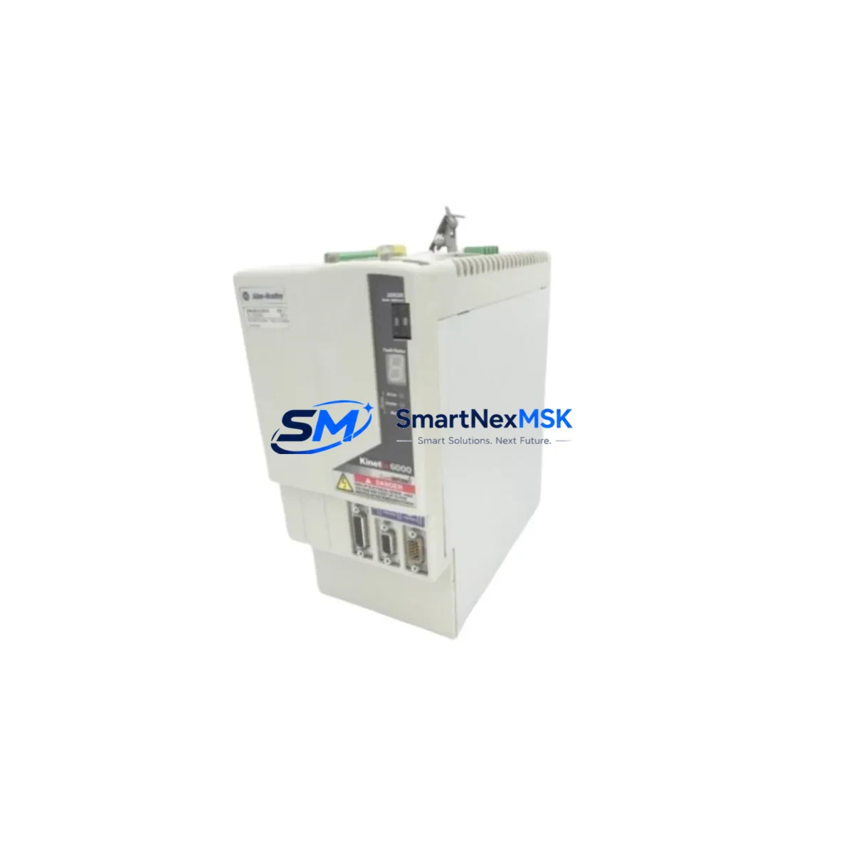
Allen-Bradley 2094-BC02-M02-S Retrofit-Ready IAM for Kinetix 6000 Control Systems
The Allen-Bradley 2094-BC02-M02-S is a dual-axis Integrated Axis Module (IAM) designed for the Kinetix 6000 multi-axis servo drive system. As legacy Kinetix 6000 infrastructure reaches end-of-life and spare parts become increasingly scarce, this module remains one of the most sought-after retrofit and replacement components for manufacturers operating Allen-Bradley motion control platforms. Whether you are restoring a failed drive system, upgrading a control cabinet, or executing a planned migration from an older Kinetix 2000 or Kinetix 6200 architecture, the 2094-BC02-M02-S delivers the power density, bus compatibility, and firmware alignment required for a smooth, low-risk transition.
This IAM integrates the converter and inverter functions into a single module, reducing cabinet footprint and simplifying wiring during retrofit projects. It operates on the Sercos interface, making it fully compatible with ControlLogix and CompactLogix controllers running Studio 5000 Logix Designer. Engineers replacing a failed 2094-BC01-M01-S or stepping up from a single-axis configuration will find the 2094-BC02-M02-S a direct form-factor match for standard 2094 series power rails and 2094-XL75S-C1 or 2094-XL75S-C3 line interface modules.
Upgrade Compatibility Table
| Parameter | Details |
|---|---|
| SKU / Part Number | 2094-BC02-M02-S |
| Series | Kinetix 6000 |
| Module Type | Integrated Axis Module (IAM) — Dual Axis |
| Communication Interface | Sercos (fiber optic ring) |
| Compatible Power Rail | 2094 series (e.g. 2094-PRS7, 2094-PRF7P) |
| Compatible LIM | 2094-XL75S-C1, 2094-XL75S-C3 |
| Compatible Controllers | ControlLogix (1756-L6x, 1756-L7x), CompactLogix |
| Direct Replacement For | 2094-BC02-M02-S (same revision), 2094-BC01-M01-S (single-to-dual upgrade) |
| Installation Requirement | Mounts on 2094 series power rail; no additional adapter required |
| Firmware Compatibility | Studio 5000 Logix Designer v20 and above |
| Wiring Compatibility | Motor feedback (2090-XXNFMF-Sxx cables), power (2090-CPWM7DF-16AFxx) |
| Commissioning Note | Axis properties and drive parameters must be re-entered or restored from RSLogix 5000 backup |
| Warranty | 12 Months — covers manufacturing defects and functional failure under normal operating conditions |
Retrofit Planning for Existing Automation Systems
A successful retrofit of the 2094-BC02-M02-S begins well before the module arrives on-site. Engineers should first audit the existing power rail configuration, confirming that the 2094 series backplane is structurally sound and that the line interface module — typically a 2094-XL75S-C1 or 2094-XL75S-C3 — is functioning correctly. The LIM governs AC input conditioning and bus pre-charge; a degraded LIM will cause nuisance faults even with a new IAM installed.
Next, verify the Sercos fiber ring topology. The 2094-BC02-M02-S communicates via Sercos optical fiber, and any degraded or contaminated fiber connectors between the 1756-M08SE or 1756-M16SE Sercos interface card and the drive modules will prevent axis initialization. Clean all fiber terminations and confirm ring continuity before powering up the replacement module.
Motor feedback cables — particularly 2090-XXNFMF-Sxx series — should be inspected for connector wear, especially at the motor junction. Damaged feedback cables are a common root cause of encoder fault codes that are incorrectly attributed to the drive module itself. Similarly, motor power cables such as 2090-CPWM7DF-16AFxx should be checked for insulation integrity before reconnection.
For sites running companion axis modules (CAM) such as the 2094-BM02-S alongside the IAM, confirm that the CAM firmware revision is compatible with the replacement IAM. Mismatched firmware between IAM and CAM units on the same power rail is a known source of axis configuration errors during commissioning. If the existing CAM is also aging, proactive replacement during the same maintenance window eliminates a second unplanned outage.
Control cabinet upgrades often involve simultaneous replacement of the 1756-L71 or 1756-L73 ControlLogix processor and the associated 1756-A7 or 1756-A13 chassis. When the controller is being replaced as part of the same project, export the existing RSLogix 5000 or Studio 5000 program before any hardware changes, and verify that the axis configuration tags — including drive model, motor catalog number, and feedback device type — are correctly mapped in the new project file. HMI screens built on PanelView Plus terminals referencing axis status tags should be validated against the updated tag database to prevent display errors after cutover.
For facilities migrating from DeviceNet or DH+ communication backbones to EtherNet/IP, the 2094-BC02-M02-S retrofit is frequently paired with a 1756-EN2T or 1756-EN3TR EtherNet/IP communication module upgrade in the ControlLogix chassis. This communication migration, when planned alongside the drive replacement, allows the facility to consolidate diagnostic visibility into a single Ethernet-based network and simplifies future remote monitoring integration.
Downtime Control During System Migration
Minimizing production downtime during a Kinetix 6000 IAM replacement requires a structured pre-outage preparation protocol. Before the maintenance window opens, the engineering team should complete a full backup of the Studio 5000 project, including all motion group configurations, axis properties, cam profiles, and coordinated motion sequences. This backup should be stored both on the programming laptop and on a network share accessible to the site’s automation team.
During the outage, follow a defined sequence: de-energize the drive system using the proper lockout/tagout procedure, discharge the DC bus through the LIM’s built-in discharge resistor circuit, remove the failed IAM from the power rail, and seat the replacement 2094-BC02-M02-S firmly until the rail connector is fully engaged. Reconnect all motor feedback and power cables, restore fiber connections, and re-energize in stages — AC input first, then DC bus pre-charge, then axis enable.
After power-up, download the saved Studio 5000 project to the controller and perform an axis properties verification for each axis served by the new IAM. Run a manual jog test at low speed before enabling any automatic sequences. For multi-axis systems where the IAM controls two servo axes simultaneously, test each axis independently before enabling coordinated motion. This staged commissioning approach protects the original program logic and ensures that no axis runs an unverified motion profile during the first powered cycle.
Sites with 24/7 production schedules should consider maintaining a pre-configured spare 2094-BC02-M02-S on the shelf, pre-loaded with the correct firmware revision and pre-tested against a known-good power rail, to reduce mean time to repair (MTTR) to under two hours for future failures.
Retrofit Support FAQ
Q: Is the 2094-BC02-M02-S a direct drop-in replacement for a failed unit of the same part number?
A: Yes. The 2094-BC02-M02-S is a form-fit-function replacement for any unit of the same catalog number. Motor power cables, feedback cables, and fiber connections reuse existing terminations. Axis parameters must be re-entered or restored from a Studio 5000 project backup, as drive parameters are not stored on the power rail.
Q: Can this IAM replace a 2094-BC01-M01-S single-axis module?
A: The 2094-BC02-M02-S occupies the same slot width on the 2094 power rail and can physically replace a single-axis IAM. However, the dual-axis capability requires that both axes be configured in the Studio 5000 project. If only one axis is needed, the second axis can be left unconfigured without affecting system operation.
Q: What commissioning steps are required after installation?
A: After seating the module and reconnecting all cables, download the Studio 5000 project to the controller, verify axis properties (motor catalog, feedback type, drive model), perform a manual jog test on each axis at reduced speed, and confirm no active faults before enabling automatic operation. For Sercos-based systems, verify node address assignment matches the original configuration.
Q: What does the 12-month warranty cover?
A: The 12-month warranty covers manufacturing defects and functional failure under normal operating conditions from the date of shipment. Each unit undergoes pre-shipment functional testing. Warranty claims are supported by our technical team at [email protected]. Physical damage caused by incorrect installation, overvoltage, or environmental contamination is excluded from warranty coverage.
© 2026 SMARTNEXMSK. All rights reserved.
Original Source: https://smartnexmsk.com
Contact: [email protected] | +86 18259474341



