
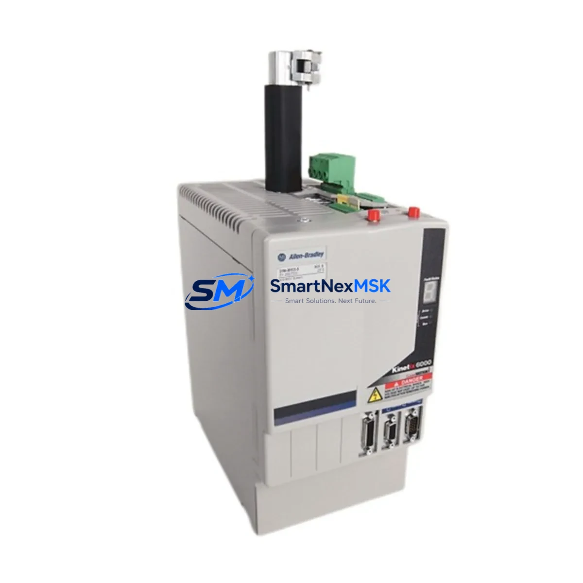
Allen-Bradley 2094-BM03-S Kinetix 6000 Maintenance-Ready Spare: Servo Axis Module for Industrial Downtime Recovery
The Allen-Bradley 2094-BM03-S is a Bulletin 2094 Integrated Axis Module (IAM) designed for the Kinetix 6000 multi-axis servo drive system. In industrial automation environments — from automotive assembly lines to packaging machinery and material handling conveyors — an unexpected servo axis failure can halt production within minutes. Stocking a verified, tested 2094-BM03-S spare is one of the most effective strategies a maintenance team can implement to minimize mean time to repair (MTTR) and protect OEE targets.
This unit is sourced as an original Allen-Bradley component, fully inspected and function-tested prior to shipment. It ships with a 12-month warranty covering manufacturing defects and operational failures under normal industrial use conditions. Every unit undergoes pre-shipment electrical verification to confirm output integrity, communication bus response, and axis enable functionality before leaving our facility.
Spare Maintenance Table
| Parameter | Specification / Detail |
|---|---|
| Part Number | 2094-BM03-S |
| Brand | Allen-Bradley (Rockwell Automation) |
| Series | Kinetix 6000 (Bulletin 2094) |
| Module Type | Integrated Axis Module (IAM) — Servo Drive Axis |
| Continuous Output Current | 3 Arms |
| Bus Voltage | 195–528 VAC, 3-phase input |
| Communication Interface | SERCOS fiber-optic ring (SERCOS II) |
| Compatibility | Kinetix 6000 drive system; pairs with 2094-BC01-MP5 or 2094-BC02-M02 power rail |
| Mounting | Bulletin 2094 power rail slot mount |
| Operating Temperature | 0–50 °C (32–122 °F) |
| Protection Rating | IP20 (panel-mount, control cabinet installation) |
| Feedback Support | High-resolution encoder, resolver, and SFD (Single Feedback Device) |
| Application Environment | Industrial control cabinets, servo motion systems, multi-axis coordinated motion |
| Maintenance Recommendation | Inspect bus connectors, fiber-optic cables, and power rail contacts at each planned maintenance interval |
| Warranty | 12 Months — covers manufacturing defects and operational failure under normal use |
| Pre-Shipment Testing | Electrical verification, axis enable test, SERCOS communication check |
| Condition | Original spare — inspected and tested |
Maintenance Planning for Continuous Operation
When a 2094-BM03-S axis module is flagged for replacement during a planned shutdown or emergency fault response, experienced maintenance engineers know that the axis module itself is rarely the only component that warrants attention. A thorough inspection of the surrounding system is essential to prevent repeat failures and ensure the replacement unit operates reliably from day one.
Begin with the Kinetix 6000 power rail (2094-BC01-MP5 or 2094-BC02-M02) — inspect the slot contacts for oxidation, mechanical damage, or loose seating. A degraded power rail connection is a common root cause of axis module faults that are misdiagnosed as module failures. Next, verify the 2094-PRS7 or 2094-PRF7 power rail filter for signs of thermal stress or capacitor bulging.
The SERCOS fiber-optic ring cables connecting the axis modules should be inspected for bend radius violations, connector contamination, and signal attenuation. A dirty or cracked fiber connector can cause intermittent SERCOS communication faults that mimic axis module failures. While the cabinet is open, check the 2094-XL75S-C1 or equivalent shunt module for proper operation — a failed shunt can cause bus overvoltage faults that damage replacement axis modules prematurely.
On the motor side, inspect the servo motor feedback cable and the motor power cable for insulation damage, connector pin corrosion, and shield continuity. Feedback cable degradation is a leading cause of encoder fault codes (E-code faults) that appear after an axis module swap. If the system uses a 2090-series feedback cable, verify the connector seating at both the motor and the axis module.
For the control side, review the ControlLogix or CompactLogix controller (such as a 1756-L71 or 1769-L33ER) and its 1756-M02AE or 1756-M08SE SERCOS motion module for firmware compatibility with the replacement 2094-BM03-S. Mismatched firmware between the motion controller and the axis module is a documented source of commissioning delays after spare part replacement. Also inspect the 24 VDC control power supply feeding the axis module enable circuit — an undersized or aging power supply can cause nuisance enable faults on the new module.
Finally, review the safety relay or safety controller wiring connected to the axis module’s safe torque-off (STO) inputs. Loose STO wiring is a frequent cause of unexpected axis inhibit faults after maintenance. Documenting and verifying all of these adjacent components as part of a structured maintenance checklist ensures the 2094-BM03-S replacement delivers maximum uptime and prevents repeat service calls.
Site Replacement Workflow
Replacing a 2094-BM03-S in the field follows a structured sequence to minimize downtime and avoid configuration errors. Before removing the faulted module, use Studio 5000 Logix Designer to export the axis configuration parameters — including tuning gains, feedback device settings, and motion scaling — so they can be restored to the replacement unit without re-commissioning from scratch.
Power down the drive system following the Kinetix 6000 installation manual lockout/tagout procedure. Discharge the DC bus fully before handling the axis module — the bus capacitors retain hazardous voltage for several minutes after power removal. Slide the faulted 2094-BM03-S out of the power rail slot, transfer the fiber-optic cables and motor connectors to the replacement unit, and seat the new module firmly until the rail latch engages.
On power-up, verify that the SERCOS ring initializes correctly (Phase 4 operation) and that the axis module node address matches the original configuration. Restore the exported axis parameters via the controller download, perform a low-speed jog test to confirm feedback polarity and motor direction, and then return the axis to automatic operation. This workflow typically allows a trained maintenance technician to complete a 2094-BM03-S swap in under two hours, significantly reducing unplanned downtime compared to waiting for OEM field service.
For legacy Kinetix 6000 systems approaching end-of-life, stocking one or two 2094-BM03-S spare modules — alongside compatible power rail filters and fiber-optic patch cables — is a proven strategy for extending system service life by five or more years without a full drive system upgrade.
Spare Parts Support FAQ
Q1: Is the 2094-BM03-S compatible with all Kinetix 6000 power rail configurations?
The 2094-BM03-S is compatible with Bulletin 2094 power rails including the 2094-BC01-MP5 and 2094-BC02-M02. It is not interchangeable with Kinetix 6200 or Kinetix 6500 series hardware. Always verify the power rail catalog number and slot configuration before ordering.
Q2: What pre-shipment testing is performed on each unit?
Each 2094-BM03-S undergoes electrical verification of bus input integrity, axis enable circuit continuity, and SERCOS communication port function. Units that do not pass all test criteria are not shipped. A test report summary is available upon request for critical spare applications.
Q3: How should the 2094-BM03-S be stored as a long-term spare?
Store in original anti-static packaging in a dry, temperature-controlled environment (10–40 °C, <85% RH non-condensing). Avoid storage near strong magnetic fields or high-vibration areas. Inspect the unit annually and power-cycle it if possible to maintain capacitor health during extended storage periods exceeding 12 months.
Q4: What is covered under the 12-month warranty?
The 12-month warranty covers manufacturing defects and operational failures under normal industrial use conditions from the date of shipment. It does not cover damage resulting from incorrect installation, overvoltage events, physical impact, or use outside the published electrical ratings. Warranty claims are processed with a return authorization and typically resolved within 5–7 business days.
© 2026 SMARTNEXMSK. All rights reserved.
Original Source: https://smartnexmsk.com
Contact: [email protected] | +86 18259474341



