
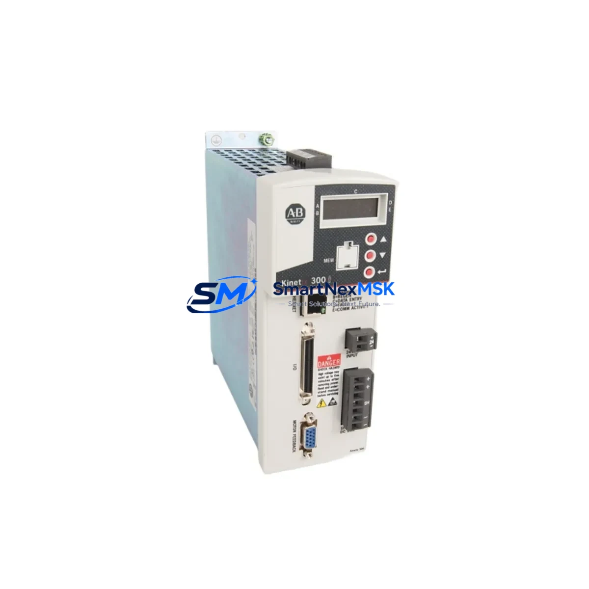
Allen-Bradley 2097-V33PR3-LM Retrofit-Ready Servo Drive for Kinetix 300 Control Systems
The Allen-Bradley 2097-V33PR3-LM is a single-axis EtherNet/IP servo drive from the Kinetix 300 series, designed for precise motion control in industrial automation environments. As legacy Kinetix 300 installations age and original components reach end-of-life, the 2097-V33PR3-LM has become a critical retrofit and replacement solution for engineers managing aging servo systems across manufacturing, packaging, material handling, and process automation lines.
This drive supports 200–240V AC single-phase input and is rated for continuous output current suitable for mid-range servo motor applications. Its native EtherNet/IP communication interface allows seamless integration with existing Logix-based control architectures, including ControlLogix and CompactLogix platforms, without requiring protocol converters or gateway hardware. When replacing a failed or discontinued axis drive, the 2097-V33PR3-LM can be installed into the existing control cabinet with minimal rewiring, provided the terminal block pinout and power supply ratings are verified against the original installation drawings.
Upgrade Compatibility Table
| Parameter | Details |
|---|---|
| SKU / Catalog Number | 2097-V33PR3-LM |
| Series | Kinetix 300 |
| Axes | Single-Axis |
| Communication Protocol | EtherNet/IP |
| Input Voltage | 200–240V AC, Single-Phase |
| Mounting | Panel / Cabinet Mount |
| Backplane Interface | Standalone (no backplane required) |
| Compatible Controllers | ControlLogix, CompactLogix (Studio 5000 / RSLogix 5000) |
| Replacement Compatibility | Direct replacement for same-series 2097-Vxx drives with matching power rating |
| Commissioning Tool | Motion Analyzer, Studio 5000 Logix Designer |
| Retrofit Complexity | Low–Medium (terminal mapping and axis tag reassignment required) |
| Warranty | 12 Months from date of shipment |
Retrofit Planning for Existing Automation Systems
When integrating the 2097-V33PR3-LM into an existing Kinetix 300 installation, the retrofit process typically begins with a power capacity audit of the control cabinet. Engineers must confirm that the 24VDC control power supply — often a 1606-XLP or equivalent Allen-Bradley power supply — can sustain the inrush and steady-state demands of the replacement drive alongside other active modules. The AC input circuit breaker rating and wiring gauge should also be verified before energizing the new unit.
Terminal block wiring is a critical checkpoint. The 2097-V33PR3-LM uses a standard feedback connector for the servo motor encoder, and the motor power terminals must be matched to the existing cable harness. If the original installation used a 2090-series motor cable, compatibility should be confirmed against the motor catalog number. In multi-axis cabinets, the drive shares the control enclosure with other components such as a 2097-V31PR0 or 2097-V32PR2 axis module, and each drive’s node address must be assigned uniquely on the EtherNet/IP network to avoid address conflicts.
On the software side, the axis configuration in Studio 5000 Logix Designer must be updated to reflect the new drive’s firmware version and motor parameters. If the original axis was configured using an older RSLogix 5000 project, the axis properties — including torque limits, velocity scaling, and feedback device type — should be reviewed and re-validated. The associated HMI screens built in FactoryTalk View or PanelView Plus terminals may reference axis status tags that need to be remapped if the controller slot or axis number changes during the retrofit.
For systems that also include a 1756-M02AE or 1756-M08SE motion module in a ControlLogix rack, the EtherNet/IP connection parameters for the 2097-V33PR3-LM must be configured to match the existing motion group scan rate. Communication link integrity should be tested using RSLinx Classic or Studio 5000’s online diagnostics before initiating any motion commands. In installations where a 1783-US8T or similar managed switch handles the motion network, VLAN and QoS settings should be reviewed to ensure deterministic packet delivery to the new drive node.
Downtime Control During System Migration
Minimizing production downtime during a servo drive replacement requires a structured pre-swap preparation process. Before removing the failed 2097-V33PR3-LM or its predecessor, the original axis configuration should be exported from Studio 5000 and saved offline. This preserves all tuning parameters, motion profiles, and cam tables that would otherwise need to be re-entered manually after the swap.
Where possible, the replacement drive should be pre-configured on a bench using a laptop with Studio 5000 and a USB-to-Ethernet adapter before it is installed in the cabinet. This allows the firmware to be updated, the motor catalog number to be entered, and the IP address to be assigned in advance — reducing live cabinet time to a physical swap and cable reconnection. Once installed, a controlled jog test at reduced speed should be performed before returning the axis to automatic mode, confirming that encoder feedback, torque response, and fault behavior all match the original system specification.
For critical production lines where even brief interruptions are costly, maintaining a spare 2097-V33PR3-LM in inventory — pre-configured and tested — is the most effective strategy for protecting control system continuity. Our stock is tested prior to shipment and backed by a 12-month warranty, ensuring that your spare is ready to deploy the moment it is needed.
Retrofit Support FAQ
Q: Is the 2097-V33PR3-LM a direct drop-in replacement for other Kinetix 300 single-axis drives?
A: It is a direct replacement for drives with the same power rating and input voltage within the 2097-V3x series. Drives with different current ratings (e.g., 2097-V31PR0 or 2097-V34PR6) are not electrically interchangeable, though they share the same commissioning workflow and software interface.
Q: What commissioning steps are required after installation?
A: After physical installation and cable connection, you must assign the drive’s IP address, update the axis properties in Studio 5000 to match the motor catalog number, run autotune if the motor has changed, and verify all safety and fault configurations before enabling the axis. A test jog at reduced speed is strongly recommended before returning to production.
Q: Can the existing motor cable and feedback wiring be reused?
A: In most cases, yes — provided the motor catalog number and cable series (typically 2090-series) are unchanged. Always verify the feedback connector pinout against the drive’s installation manual before powering up to avoid encoder damage.
Q: What does the 12-month warranty cover?
A: The 12-month warranty covers manufacturing defects and functional failures under normal operating conditions from the date of shipment. Each unit undergoes pre-shipment functional testing. Warranty claims are supported directly through our sales team with fast replacement dispatch to minimize your downtime.
© 2026 SMARTNEXMSK. All rights reserved.
Original Source: https://smartnexmsk.com
Contact: [email protected] | +86 18259474341



