
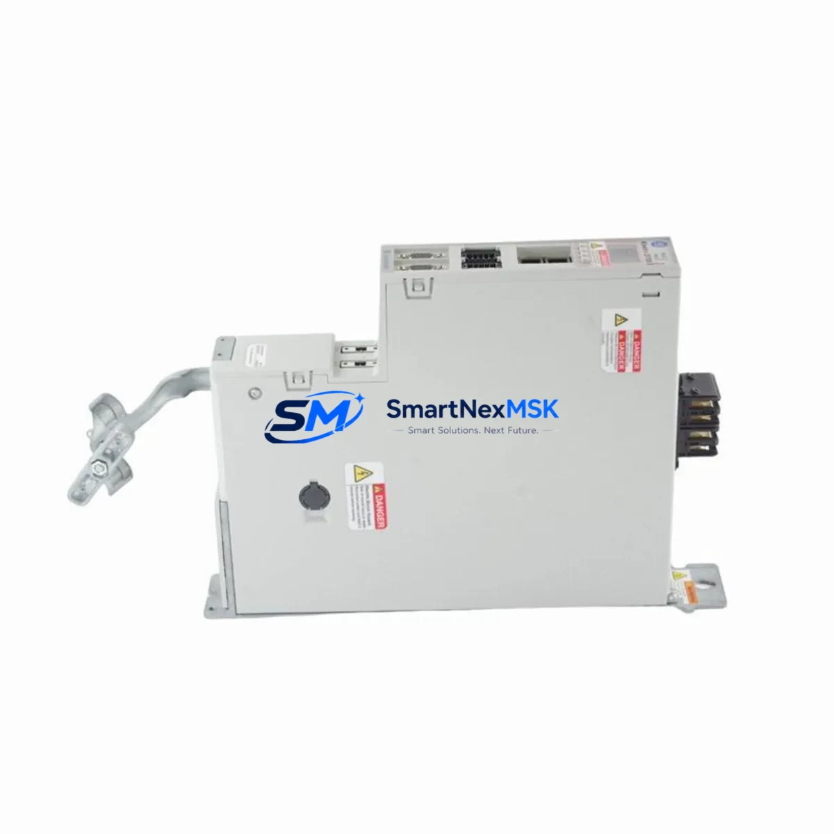
Allen-Bradley 2198-D006-ERS3 Retrofit-Ready Dual-Axis Servo Drive for Kinetix 5700 Control Systems
The Allen-Bradley 2198-D006-ERS3 is a dual-axis EtherNet/IP servo drive module within the Kinetix 5700 series, designed for high-performance motion control in demanding industrial automation environments. As legacy Kinetix 5500 and Kinetix 6500 installations reach end-of-life, the 2198-D006-ERS3 has become a primary retrofit target for engineers modernizing multi-axis servo systems without replacing the entire control cabinet. This module supports 3-phase 460–480V AC input, delivers up to 6A continuous output per axis, and integrates natively with Studio 5000 Logix Designer via the CIP Motion over EtherNet/IP protocol — making it a seamless upgrade path for existing ControlLogix and CompactLogix platforms.
When planning a retrofit from an older Kinetix 5500 (2198-Hxxx) or Kinetix 6500 (2094-BCxx) drive, engineers must verify that the replacement 2198-D006-ERS3 shares the same DC bus architecture. The Kinetix 5700 series uses a shared DC bus topology, meaning the 2198-D006-ERS3 must be paired with a compatible 2198-Pxxx DC bus power supply — such as the 2198-P031 or 2198-P070 — rather than individual AC input power supplies used in earlier generations. Confirming bus power capacity before installation is critical to avoid nuisance faults during acceleration peaks.
Terminal wiring compatibility is another key consideration. The 2198-D006-ERS3 uses the standard Kinetix 5700 motor feedback connector pinout, supporting both single-turn and multi-turn absolute encoders via the 2090-CFBM7DF-CEAAxx feedback cable family. If the existing servo motors are Bulletin MPL, MPM, or VPL series with Hiperface or EnDat 2.2 feedback, the feedback cables are typically reusable without modification — significantly reducing retrofit labor. However, if the legacy system used resolver-based feedback (common in older Kinetix 6000 installations), a feedback converter or motor replacement will be required.
Upgrade Compatibility Table
| Parameter | Legacy (Kinetix 5500 / 6500) | 2198-D006-ERS3 (Kinetix 5700) |
|---|---|---|
| Communication Protocol | EtherNet/IP (CIP Motion) | EtherNet/IP (CIP Motion) ✓ Compatible |
| DC Bus Architecture | Individual AC Input | Shared DC Bus — requires 2198-Pxxx PSU |
| Backplane / Mounting | Kinetix 5500 rail mount | Kinetix 5700 DC bus bar — verify rail spacing |
| Motor Feedback | Hiperface / EnDat / Resolver | Hiperface / EnDat 2.2 ✓ (Resolver requires adapter) |
| Studio 5000 Compatibility | v20.x and above | v28.x and above recommended |
| Module Address / Axis Tag | Existing axis tags reusable | Re-map axis tags in controller project |
| HMI Screen Updates | May reference legacy drive faults | Update fault codes in FactoryTalk View SE/ME |
| Installation Footprint | Varies by model | Verify panel depth and bus bar clearance |
| Warranty | — | 12-Month Warranty included |
| Replacement Recommendation | Kinetix 5500 2198-H003-ERS / 2198-H008-ERS | Direct upgrade to 2198-D006-ERS3 with bus PSU |
Retrofit Planning for Existing Automation Systems
A successful retrofit centered on the 2198-D006-ERS3 typically begins with a full audit of the existing control cabinet. Engineers should document the current DC bus power supply rating, the number of axes sharing the bus, and the peak regenerative load — particularly in applications with high-inertia loads such as winding machines, gantry systems, or rotary indexers. The 2198-P031 bus power supply supports up to 31kW of bus power, while the 2198-P070 extends this to 70kW for larger multi-axis configurations.
On the controller side, the ControlLogix L8x or CompactLogix 5380 running the motion program must be verified for firmware compatibility. Studio 5000 v28 or later is required to support the full Kinetix 5700 axis parameter set, including the integrated safety functions (STO, SS1, SLS) available on ERS3-variant drives. If the existing project was developed in an earlier version, a firmware upgrade of the 1756-L8x controller and a project migration in Studio 5000 will be necessary before commissioning the 2198-D006-ERS3.
The I/O architecture should also be reviewed. In many legacy installations, discrete I/O from a 1756-IB16 or 1734-IB8 POINT I/O module handles drive enable, fault reset, and home switch signals. These wiring connections are generally preserved during a Kinetix 5700 retrofit, as the drive’s digital inputs accept the same 24VDC logic levels. However, if the legacy system used a 2090-UXBB-Dxx breakout board for terminal wiring, verify that the new drive’s I/O connector pinout matches before reusing existing wiring harnesses.
Communication link integrity is equally important. The 2198-D006-ERS3 connects to the EtherNet/IP network via a standard RJ45 port and supports both linear and Device Level Ring (DLR) topologies. If the existing network uses a 1783-ETAP tap or a Stratix 5700 managed switch, no infrastructure changes are required. The drive’s IP address is assigned via BOOTP/DHCP or set statically through the Logix Designer Add-On Profile (AOP), which must be updated to the Kinetix 5700 AOP version compatible with your Studio 5000 release.
Downtime Control During System Migration
Minimizing production downtime during a Kinetix 5700 retrofit requires a structured pre-commissioning strategy. Before the scheduled maintenance window, engineers should complete the Studio 5000 project migration offline, update all axis parameters, and simulate the motion program using Logix Designer’s offline emulation tools. The existing program logic — including motion instructions (MAM, MAS, MASD, MAFR), cam profiles, and coordinated motion groups — is fully compatible with the Kinetix 5700 platform, provided axis tags are correctly remapped to the new drive’s Add-On Profile.
During the physical swap, the DC bus bar connections should be made with the bus power supply (2198-Pxxx) de-energized and locked out per LOTO procedures. The 2198-D006-ERS3 slots onto the shared bus bar and is secured with the standard Kinetix 5700 mounting hardware — no custom brackets or panel modifications are required in most standard cabinet layouts. Motor power and feedback cables connect to the drive’s bottom connectors, and if the existing 2090-series cables are in good condition, they can be reused directly.
After physical installation, the commissioning sequence follows the standard Kinetix 5700 startup procedure: verify bus voltage, enable the drive via the controller, run the Motor Feedback Test, and execute the Tune axis function in Studio 5000 to establish the velocity and position loop gains. For systems where the original tuning parameters are documented, these can be entered manually to reduce auto-tune time and protect existing process performance. A final functional test — including fault injection, STO verification, and a full motion cycle at reduced speed — should be completed before returning the line to production. All units supplied by SMARTNEXMSK are pre-tested prior to shipment and covered by a 12-month warranty, ensuring confidence in the replacement component before it enters your system.
Retrofit Support FAQ
Q1: Can the 2198-D006-ERS3 directly replace a Kinetix 5500 2198-H003-ERS or 2198-H008-ERS drive?
The 2198-D006-ERS3 is not a pin-for-pin drop-in for Kinetix 5500 drives due to the DC bus architecture difference. The Kinetix 5700 requires a shared DC bus power supply (2198-Pxxx), whereas Kinetix 5500 drives use individual AC input. The motion control logic, EtherNet/IP communication, and motor feedback wiring are compatible, but the power supply and bus bar infrastructure must be updated as part of the retrofit.
Q2: What Studio 5000 version and controller firmware are required?
Studio 5000 Logix Designer v28.00 or later is required for full Kinetix 5700 support. The ControlLogix L8x or CompactLogix 5380 controller should be running firmware v28 or above. The Kinetix 5700 Add-On Profile (AOP) must be installed in Studio 5000 and matched to the drive’s firmware version. Mismatched AOP and firmware versions are a common source of commissioning faults and should be verified before the maintenance window.
Q3: How is the drive’s wiring and terminal compatibility verified before installation?
Review the 2198-D006-ERS3 installation manual (Rockwell publication 2198-IN001) for connector pinouts and compare against the existing wiring documentation. Key connectors include the motor power (MP) connector, the motor feedback (MF) connector, and the I/O connector. If the existing system uses 2090-CFBM7DF-CEAAxx feedback cables and Bulletin MPL/VPL motors, these are directly compatible. All units from SMARTNEXMSK are inspected and function-tested prior to shipment, and our technical team can assist with wiring verification before installation.
Q4: What does the 12-month warranty cover, and what is the return process?
The 12-month warranty covers manufacturing defects and functional failures under normal operating conditions. It does not cover damage caused by incorrect installation, overvoltage, or environmental factors outside the drive’s rated specifications. In the event of a warranty claim, contact SMARTNEXMSK with the order reference and a description of the fault. Replacement or repair will be arranged with priority handling to minimize your production downtime. Pre-shipment testing documentation is available upon request.
© 2026 SMARTNEXMSK. All rights reserved.
Original Source: https://smartnexmsk.com
Contact: [email protected] | +86 18259474341



