
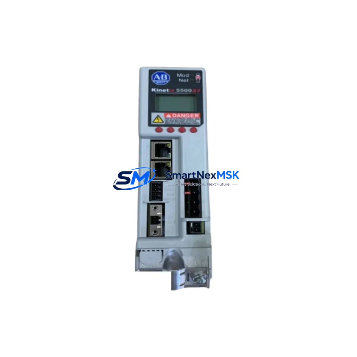
Allen-Bradley 2198-P070 Spare for Kinetix 5500 Automation: Spare Parts Replacement & Downtime Risk Control
The Allen-Bradley 2198-P070 is a 70 kW Shared DC Bus Power Supply designed for the Kinetix 5500 servo drive system. As a critical power infrastructure component in multi-axis motion control cabinets, the 2198-P070 directly governs DC bus voltage stability across all connected Kinetix 5500 axis modules. Unplanned failure of this unit results in immediate shutdown of the entire servo drive network — making rapid, verified spare availability a non-negotiable element of any industrial maintenance strategy.
This listing supplies an original, tested 2198-P070 unit, backed by a 12-month warranty and pre-shipment functional verification. Whether you are managing a planned overhaul, responding to an emergency fault, or building a proactive spare parts inventory for a multi-axis Kinetix 5500 installation, this unit ships ready for direct panel installation.
Spare Maintenance Table
| Parameter | Specification |
|---|---|
| Part Number / SKU | 2198-P070 |
| Brand | Allen-Bradley (Rockwell Automation) |
| Series | Kinetix 5500 |
| Product Type | Shared DC Bus Power Supply |
| Rated Output Power | 70 kW |
| DC Bus Architecture | Shared DC Bus (multi-axis) |
| Input Voltage | 400–480 V AC, 3-phase |
| Communication Interface | EtherNet/IP (integrated) |
| Compatible Drive Series | Kinetix 5500 (2198-Hxxx axis modules) |
| Mounting | DIN rail / panel mount, shared bus connector |
| Cooling | Forced air (internal fan) |
| Operating Temperature | 0–55 °C (ambient) |
| Protection Rating | IP20 |
| Origin | USA |
| Condition | Original, tested before shipment |
| Warranty | 12 Months |
| Compatibility Confirmation | Verified against Kinetix 5500 system architecture |
| Maintenance Recommendation | Inspect DC bus connectors, input fusing, and cooling fan annually; replace capacitors per Rockwell PM schedule |
Maintenance Planning for Continuous Operation
When a 2198-P070 fault is identified — whether through a DC bus undervoltage alarm, an axis inhibit fault, or a scheduled preventive maintenance inspection — the replacement workflow extends beyond the power supply itself. Maintenance engineers should treat this event as a full cabinet health checkpoint.
Begin with the input power circuit: verify the three-phase input fusing and the upstream circuit breaker feeding the 2198-P070. A blown fuse or nuisance trip upstream is frequently the root cause of apparent power supply failure. Next, inspect the shared DC bus connector bar and the bus capacitor bank condition — degraded capacitors in the 2198-P070 or in adjacent 2198-H040-ERS2 or 2198-H025-ERS2 axis modules can cause recurring bus faults even after a power supply swap.
Check all 2198-CAPMOD-2240 capacitor modules if your system uses regenerative bus sharing — these are wear items with defined replacement intervals. Inspect the 2198-DBXX dynamic braking resistor wiring for signs of thermal stress, as excessive regenerative energy can accelerate power supply aging.
On the control side, verify the 2198-H2DCK dual-axis connector kit integrity and the 24 V DC control power supply feeding the drive logic boards. A marginal 24 V rail — often sourced from a 1606-XLP or similar Rockwell power supply — can cause intermittent axis faults that are misdiagnosed as power supply failures.
For communication health, confirm EtherNet/IP connectivity between the 2198-P070 and the controlling CompactLogix L3x or ControlLogix L8x PLC. A degraded managed switch port or a faulty 1783-US5T Stratix switch can introduce cyclic communication faults that manifest as drive inhibit conditions. Review the Studio 5000 drive configuration backup before reinstalling the replacement unit to ensure axis parameters, scaling, and safety configurations are preserved.
Finally, inspect the 2198-H040-ERS2 axis module feedback connectors and motor power cables for insulation breakdown — particularly in high-cycle or high-temperature environments. Replacing the 2198-P070 without addressing degraded motor cables or encoder feedback wiring will result in repeat faults within weeks of restart.
Site Replacement Workflow
Step 1 — Isolate and de-energize: Open the upstream main disconnect and lockout/tagout per site LOTO procedure. Confirm DC bus voltage has discharged below 50 V DC using a calibrated meter before touching bus connectors.
Step 2 — Document configuration: Export the existing drive configuration from Studio 5000 Logix Designer. Record all axis parameters, motion group assignments, and safety task configurations. Photograph wiring before disconnection.
Step 3 — Remove the 2198-P070: Disconnect the shared DC bus connector, three-phase input wiring, 24 V control power, and EtherNet/IP cable. Remove DIN rail or panel mounting hardware.
Step 4 — Install the replacement unit: Mount the new 2198-P070, reconnect all wiring per the original documentation. Torque bus connector bolts to specification (refer to Rockwell publication 2198-IN001).
Step 5 — Power-up and verify: Restore control power first; confirm no fault LEDs. Apply three-phase input power; verify DC bus voltage rises to nominal. Download the saved configuration to the drive system and perform a motion test on each axis before returning to production.
This workflow minimizes downtime, preserves system compatibility, and ensures the replacement 2198-P070 operates within the original Kinetix 5500 system parameters without requiring re-commissioning from scratch.
Spare Parts Support FAQ
Q1: Is this 2198-P070 unit compatible with all Kinetix 5500 axis module variants?
Yes. The 2198-P070 is the shared DC bus power supply for the entire Kinetix 5500 (2198-Hxxx) axis module family. It is compatible with single-axis and dual-axis modules across the full power range of the Kinetix 5500 series. Always confirm your system’s total axis power demand does not exceed the 70 kW bus rating.
Q2: What pre-shipment testing is performed on this unit?
Each 2198-P070 unit undergoes functional power-on testing, DC bus output voltage verification, and communication interface check prior to shipment. Units that do not meet original specification are not listed. A test report is available upon request.
Q3: How should I manage long-term spare inventory for a multi-axis Kinetix 5500 system?
For systems with four or more axis modules, we recommend holding one 2198-P070 as a cold spare and maintaining at least one spare axis module matched to your highest-power axis. Capacitor modules (2198-CAPMOD-2240) and input fusing should be stocked as consumables. Review your spare parts list annually against Rockwell’s published end-of-life notices.
Q4: What is covered under the 12-month warranty?
The 12-month warranty covers manufacturing defects and functional failure under normal operating conditions. It does not cover damage resulting from incorrect installation, overvoltage events, or physical impact. Warranty claims are processed with return shipment support and replacement dispatch within 5 business days of fault confirmation.
© 2026 SMARTNEXMSK. All rights reserved.
Original Source: https://smartnexmsk.com
Contact: [email protected] | +86 18259474341



