
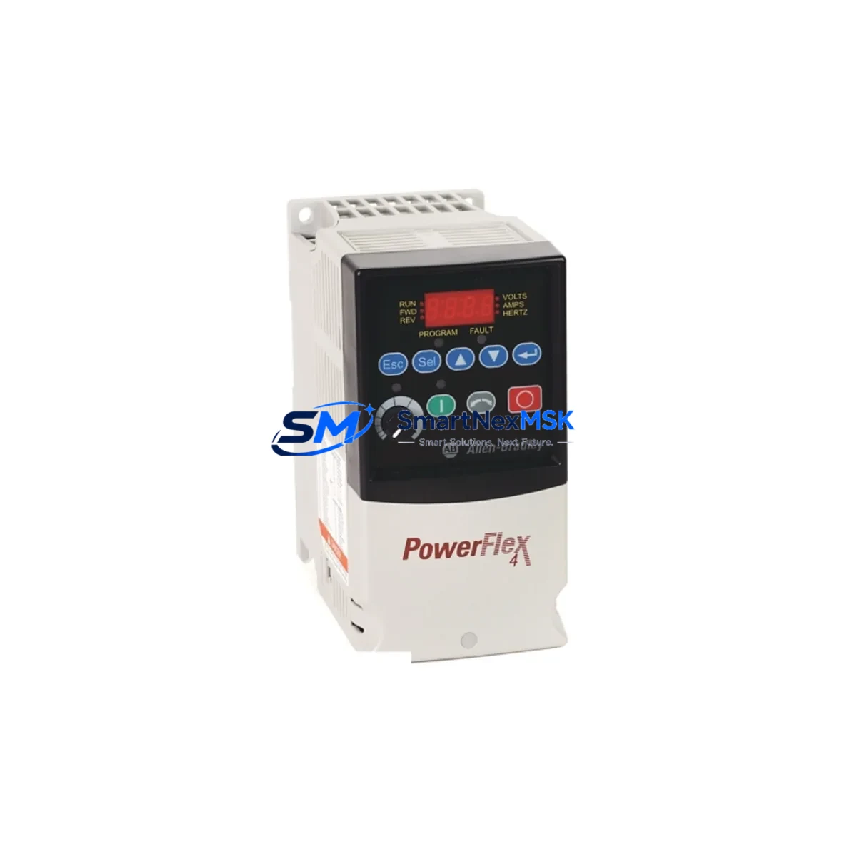
Allen-Bradley 22A-B012N104 Spare for PowerFlex 4 Automation
The Allen-Bradley 22A-B012N104 is a PowerFlex 4 series AC variable frequency drive rated at 5.5 kW (7.5 HP), 480V three-phase input, with a 12 A continuous output current. As a maintenance-ready spare, this unit is sourced to support rapid replacement in production environments where unplanned downtime carries significant operational and financial risk. Whether you are managing a planned shutdown, responding to a fault alarm, or building a critical-spares inventory for aging PowerFlex 4 installations, the 22A-B012N104 provides a direct, parameter-compatible drop-in solution that minimizes reconfiguration time on site.
Industrial maintenance teams operating Rockwell Automation control architectures rely on the PowerFlex 4 series for conveyor drives, pump control, fan speed regulation, and general-purpose motor management across light to medium industrial loads. When a 22A-B012N104 fails — whether due to DC bus overvoltage, IGBT fault, thermal shutdown, or input phase loss — the fastest path to recovery is a pre-tested, shelf-ready spare. SMARTNEXMSK stocks this model with full functional verification prior to dispatch, ensuring the unit you receive is ready for immediate installation.
Spare Maintenance Table
| Parameter | Specification |
|---|---|
| Part Number / SKU | 22A-B012N104 |
| Series | PowerFlex 4 |
| Brand | Allen-Bradley (Rockwell Automation) |
| Output Power | 5.5 kW / 7.5 HP |
| Input Voltage | 480V AC, 3-Phase, 50/60 Hz |
| Output Current | 12 A (continuous) |
| Control Mode | V/Hz, Sensorless Vector |
| Enclosure Rating | IP20 / NEMA Type 1 |
| Communication | DSI (Drive Serial Interface) compatible |
| Compatibility | PowerFlex 4 series; direct replacement for 22A-B012N104 |
| Installation | Panel mount, DIN rail adaptable |
| Operating Temperature | 0°C to 50°C (derating above 40°C) |
| Application Environment | Conveyors, pumps, fans, compressors, general industrial |
| Maintenance Recommendation | Inspect cooling fan, DC bus capacitors, and terminal connections at 12-month intervals |
| Origin | USA |
| Warranty | 12 Months from date of shipment |
| Pre-shipment Testing | Full functional verification performed before dispatch |
Maintenance Planning for Continuous Operation
Replacing a 22A-B012N104 in the field is rarely an isolated task. Experienced maintenance engineers know that a VFD fault often signals stress across adjacent components in the same electrical circuit or control cabinet. Before returning the system to service, a thorough inspection of the surrounding hardware is strongly recommended.
Start with the input power supply: verify that the incoming 480V three-phase supply is balanced and within tolerance. A persistent phase imbalance is a common root cause of premature drive failure and will damage a replacement unit if left uncorrected. Check the input line reactor or EMC filter upstream of the drive — these components protect the VFD from line transients and harmonic disturbances, and a failed filter can allow damaging voltage spikes to reach the new unit.
Inspect the motor output cables for insulation breakdown, especially in installations where cable runs exceed 30 metres or where the cable passes through conduit with other high-voltage conductors. A shorted motor cable will immediately stress the output IGBTs of the replacement drive. If the motor itself has been running under fault conditions, perform a motor insulation resistance (megger) test before reconnecting.
Within the control cabinet, examine the 24VDC control power supply that feeds the drive’s logic board and any connected I/O modules. A drooping or noisy 24V rail can cause erratic drive behaviour and spurious fault codes. Check the terminal blocks and control wiring on the DSI port — loose or corroded connections on the serial communication interface are a frequent source of intermittent faults in PowerFlex 4 installations.
If the 22A-B012N104 is integrated into a larger Rockwell Automation system, verify the status of the MicroLogix or CompactLogix PLC controlling the drive via DSI or DeviceNet. A corrupted drive parameter file or a PLC program fault can prevent the replacement drive from accepting commands even after a successful hardware swap. Review the PanelView HMI alarm history to identify any pre-existing fault patterns that may have contributed to the original failure.
For installations using safety relay modules or Safe Torque Off (STO) wiring, confirm that the STO circuit is correctly configured and that the safety relay has not latched in a fault state. Also inspect any braking resistors connected to the drive’s dynamic braking terminals — an open-circuit braking resistor will cause DC bus overvoltage faults under deceleration loads.
Finally, review the drive parameter backup. The PowerFlex 4 supports parameter upload via the 22-HIM-A3 or 22-HIM-C2S handheld programmer. If a parameter backup was taken before the failure, restoring it to the replacement 22A-B012N104 will eliminate manual re-entry errors and accelerate commissioning. If no backup exists, document all parameters during the replacement procedure to establish a baseline for future maintenance.
Site Replacement Workflow
Step 1 — Isolation and lockout: De-energise the drive using the upstream isolator or circuit breaker. Apply LOTO (Lockout/Tagout) procedure. Wait a minimum of 5 minutes for the DC bus capacitors to discharge before opening the enclosure. Verify bus voltage with a calibrated meter before touching internal terminals.
Step 2 — Document existing wiring: Photograph or sketch all terminal connections on the failed unit, including R/S/T input terminals, U/V/W motor output terminals, control terminal strip (TB1), and DSI port wiring. Note the positions of any jumpers or DIP switches.
Step 3 — Remove the failed unit: Disconnect all wiring in the documented order. Remove the drive from its mounting position. Retain all hardware for reinstallation.
Step 4 — Install the 22A-B012N104 replacement: Mount the new unit in the same position. Reconnect all wiring per the documented layout. Torque all power terminals to the manufacturer’s specification (typically 1.7–2.0 N·m for the PowerFlex 4 power terminals). Reconnect control wiring and DSI communications.
Step 5 — Parameter restore and commissioning: Power up the drive and restore parameters from backup, or manually enter the required settings (motor nameplate data, acceleration/deceleration ramps, frequency limits, and any application-specific parameters). Perform a no-load test run before reconnecting the mechanical load.
Step 6 — Return to service: Reconnect the load, perform a supervised test run at low speed, and verify current draw, speed reference tracking, and fault-free operation before handing back to production.
This workflow is designed to minimise total downtime from fault detection to production restart, typically achievable within 2–4 hours for a prepared maintenance team with a shelf-ready spare.
Spare Parts Support FAQ
Q1: Is the 22A-B012N104 a direct replacement for my existing PowerFlex 4 drive?
Yes. The 22A-B012N104 is a standard PowerFlex 4 catalogue number and is a direct hardware replacement for any unit carrying the same part number. It is parameter-compatible with all standard PowerFlex 4 firmware versions. If your existing installation uses a customised parameter set, restore it from backup after installation to ensure identical behaviour.
Q2: How do you verify the unit before shipment?
Every 22A-B012N104 dispatched by SMARTNEXMSK undergoes a full functional test including power-on self-test, DC bus charge verification, output phase balance check, and control terminal response test. A test report is available on request. Units are packed in anti-static, shock-protected packaging to prevent transit damage.
Q3: What does the 12-month warranty cover?
The 12-month warranty covers all manufacturing defects and functional failures under normal operating conditions from the date of shipment. It does not cover damage resulting from incorrect installation, overvoltage events beyond the drive’s rated input tolerance, or physical damage in transit if the original packaging has been compromised. Warranty claims are processed within 5 business days of receipt of the returned unit.
Q4: Can you supply multiple units for a critical-spares inventory programme?
Yes. SMARTNEXMSK supports bulk spare parts procurement for planned maintenance programmes and long-term service contracts. Volume pricing is available for orders of 3 or more units of the same part number. Contact our technical sales team to discuss stocking agreements, lead times, and consignment options for high-criticality PowerFlex 4 installations.
© 2026 SMARTNEXMSK. All rights reserved.
Original Source: https://smartnexmsk.com
Contact: [email protected] | +86 18259474341



