
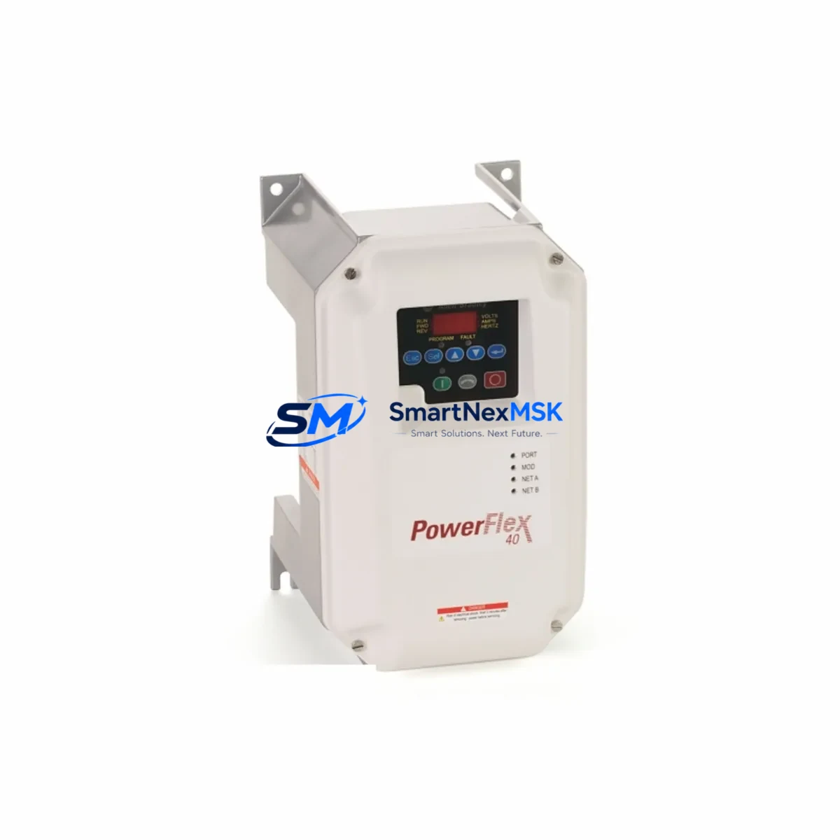
Allen-Bradley 22B-D010C104 Retrofit-Ready VFD for PowerFlex 40 Control Systems
The Allen-Bradley 22B-D010C104 is a 4kW (5HP), 3-phase, 380–480V AC variable frequency drive from the PowerFlex 40 series — one of Rockwell Automation’s most widely deployed compact drive platforms in industrial automation. Designed for motor speed control in conveyor systems, pump stations, fan arrays, and general-purpose machine control, this drive remains a critical component in legacy automation architectures across manufacturing, water treatment, and process industries worldwide.
As original equipment manufacturers phase out support for older drive generations and spare parts become increasingly difficult to source, the 22B-D010C104 serves as both a direct replacement for failed units and a retrofit-ready upgrade path for aging control panels. Whether you are restoring a production line after an unplanned drive failure or executing a planned modernization of a legacy control cabinet, this unit provides the electrical and mechanical compatibility required to minimize engineering rework and reduce total downtime.
Before installing the 22B-D010C104 as a replacement, engineers should verify several key parameters. First, confirm that the existing power supply delivers stable 3-phase 380–480V AC input within the drive’s rated tolerance. The 22B-D010C104 draws approximately 10A input current at full load, so the upstream circuit breaker and wiring gauge must be rated accordingly. Terminal block layout on the PowerFlex 40 platform is consistent across the 22B-D series, which simplifies direct terminal-for-terminal rewiring when replacing an earlier 22B-series unit such as the 22B-D6P0N104 or 22B-D012N104.
Backplane and mounting considerations are equally important. The PowerFlex 40 uses a standard DIN rail or panel-mount footprint, and the 22B-D010C104 shares the same physical envelope as other drives in the 22B-D series, making it a mechanical drop-in for most existing enclosures. If the original installation used an optional 22-XCOMM-DC-BASE DeviceNet or EtherNet/IP communication adapter, verify that the adapter firmware is compatible with the replacement unit before reconnecting the network. In DeviceNet or ControlNet topologies, the drive’s node address must be reassigned to match the original configuration stored in the PLC program — typically a Logix5000-based controller such as the CompactLogix L30E or MicroLogix 1400.
Program compatibility is a frequent concern during drive replacement. If the original drive was configured using DriveExplorer or Connected Components Workbench (CCW), parameter files can be exported and re-imported to the replacement unit via the 1203-USB or 22-SCM-232 serial programming cable. Key parameters to restore include acceleration and deceleration ramp times, minimum and maximum output frequency, motor nameplate data (voltage, current, frequency, RPM), and any custom fault response settings. Failure to restore these parameters before commissioning can result in motor overcurrent trips or process upsets during the first run.
HMI integration should also be reviewed. If the existing system uses a PanelView 800 or PanelView Plus terminal communicating with the drive over RS-485 using the DF1 or Modbus RTU protocol, the communication parameters — baud rate, parity, stop bits, and drive address — must be re-entered on the replacement unit. In EtherNet/IP-connected systems, the drive’s IP address assignment (static or DHCP) must match the original network configuration to avoid disrupting the SCADA or DCS polling cycle.
Upgrade Compatibility Table
| Parameter | Details |
|---|---|
| SKU / Part Number | 22B-D010C104 |
| Series | Allen-Bradley PowerFlex 40 |
| Power Rating | 4kW / 5HP |
| Input Voltage | 3-Phase, 380–480V AC, 50/60Hz |
| Output Current | 10A (ND) / 9.0A (HD) |
| Enclosure Rating | IP20 / NEMA Type 1 (with optional kit) |
| Mounting | DIN Rail or Panel Mount |
| Communication Options | RS-485 (DSI), optional EtherNet/IP, DeviceNet, Modbus RTU via adapter |
| Direct Replacement For | 22B-D010C104 (same series), 22B-D6P0N104, 22B-D012N104 |
| Compatible Controllers | CompactLogix, MicroLogix 1400, SLC 500 (via gateway) |
| Programming Tool | Connected Components Workbench (CCW), DriveExplorer, 1203-USB cable |
| Commissioning Check | Motor nameplate data, ramp times, frequency limits, fault response |
| Warranty | 12 Months from date of shipment |
Retrofit Planning for Existing Automation Systems
A successful retrofit begins with a thorough audit of the existing control cabinet. In a typical PowerFlex 40 installation, the drive shares the enclosure with a 1606-XLP power supply, terminal blocks, a 1492-J fuse block, and in many cases a 1734 POINT I/O adapter or 1769 CompactLogix I/O module providing digital and analog signals to the process. Before removing the failed drive, photograph all terminal wiring and record the parameter list using the drive’s integral HIM (Human Interface Module) or a laptop running CCW.
If the retrofit involves migrating from an older SLC 500 or PLC-5 platform to a CompactLogix or ControlLogix architecture, the 22B-D010C104 supports this transition natively through its DSI serial port and optional 22-COMM-E EtherNet/IP adapter. This allows the drive to participate in a modern Logix-based control network without requiring a full panel redesign. The 22-COMM-D DeviceNet adapter is also available for installations that retain a legacy DeviceNet network alongside newer EtherNet/IP segments.
I/O expansion during the retrofit should be planned carefully. If the original system used analog speed reference signals (0–10V or 4–20mA) from a 1769-IF4 or 1734-IE4C module, verify that the wiring to terminals 1 (AI1+) and 2 (AI1–) on the 22B-D010C104 is correctly shielded and grounded to prevent noise-induced speed fluctuations. Digital I/O wiring — including run/stop, fault reset, and speed preset inputs — should be verified against the original ladder logic or function block diagram before energizing the replacement drive.
For installations where the 22B-D010C104 controls a pump or fan in a water treatment or HVAC application, the PID loop parameters stored in the drive (if using the drive’s internal PID function) must be re-entered after replacement. These include the proportional gain, integral time, derivative time, and feedback source selection. If PID control is handled externally by a CompactLogix controller, only the speed reference scaling and output frequency limits need to be verified on the drive itself.
Downtime Control During System Migration
Minimizing production downtime during a drive replacement requires preparation before the maintenance window begins. The recommended approach is to pre-configure the replacement 22B-D010C104 on a bench using CCW and the 1203-USB programming cable, loading all parameters from the saved parameter file before the unit is installed in the panel. This reduces in-panel commissioning time to terminal connection, network address assignment, and a brief no-load test run.
Where a parameter backup file is not available — a common situation with legacy installations — the drive’s default parameter set provides a safe starting point. The technician should then adjust motor nameplate parameters (P031–P035), acceleration time (P041), deceleration time (P042), and minimum/maximum frequency (P043/P044) based on the motor nameplate and process requirements. A controlled test run at reduced speed (10–20Hz) before returning to full production speed allows verification of rotation direction, current draw, and fault-free operation without risking a process upset.
In networked systems, coordinate the drive replacement with the PLC programmer to temporarily place the drive’s control tag in manual mode within the Logix program, preventing the controller from issuing run commands during the swap. Once the replacement drive is confirmed operational, return the tag to automatic mode and monitor the first production cycle closely. This approach protects the original program logic and maintains field control continuity throughout the migration.
Retrofit Support FAQ
Q: Is the 22B-D010C104 a direct drop-in replacement for other 22B-D series drives?
A: Yes. The 22B-D010C104 shares the same physical footprint, terminal layout, and parameter structure as other drives in the PowerFlex 40 22B-D series, including the 22B-D6P0N104 and 22B-D012N104. Terminal-for-terminal rewiring is straightforward, and parameter files from the original unit can be imported directly using CCW or DriveExplorer.
Q: What commissioning steps are required after installation?
A: After wiring, restore the motor nameplate data (voltage, current, frequency, RPM, power factor), set acceleration/deceleration ramps, configure the speed reference source (keypad, analog input, or network), and verify the communication adapter settings if applicable. Perform a no-load test run before connecting the motor load.
Q: How do I verify communication compatibility with my existing PLC network?
A: Confirm the communication adapter type (22-COMM-E for EtherNet/IP, 22-COMM-D for DeviceNet, or 22-COMM-C for ControlNet) matches the original installation. Reassign the drive’s network node address or IP address to match the original configuration. Verify the EDS file version in the PLC’s I/O tree matches the adapter firmware version.
Q: What does the 12-month warranty cover?
A: All units are tested prior to shipment and covered by a 12-month warranty from the date of shipment against manufacturing defects and functional failures under normal operating conditions. Warranty support includes technical assistance for installation and commissioning. Contact [email protected] for warranty claims or pre-shipment testing documentation.
© 2026 SMARTNEXMSK. All rights reserved.
Original Source: https://smartnexmsk.com
Contact: [email protected] | +86 18259474341



