
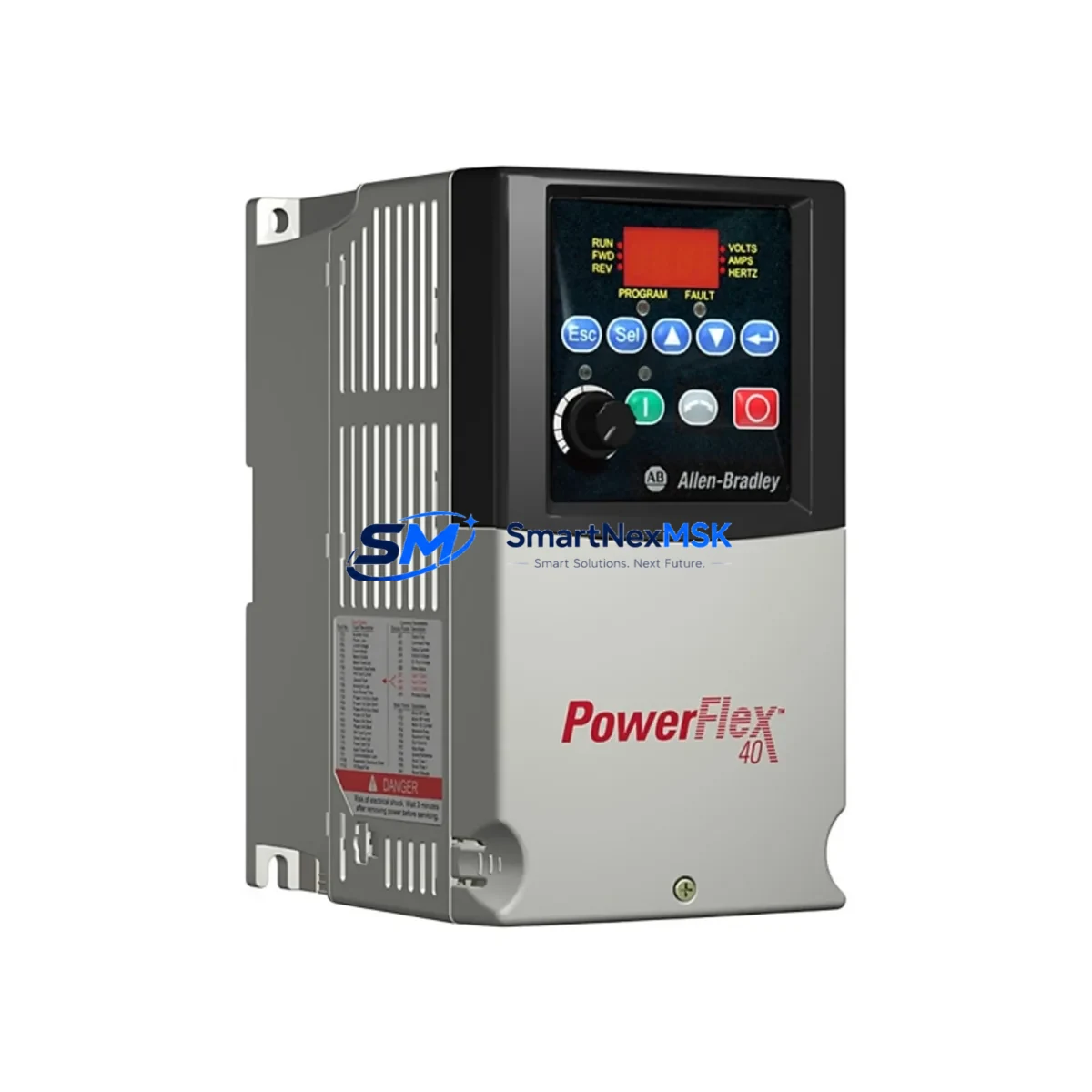
Allen-Bradley 22B-D010N104 Spare PowerFlex 40 Drive: Spare Replacement & Industrial Downtime Risk Control
The Allen-Bradley 22B-D010N104 is a 4kW (5HP) PowerFlex 40 series AC variable frequency drive designed for 3-phase 380–480V industrial motor control applications. As a maintenance-ready original spare, this unit is critical for facilities running conveyor systems, pump stations, HVAC equipment, and general-purpose motor loads where unplanned downtime carries significant operational cost. Sourced as an original spare and tested prior to shipment, the 22B-D010N104 supports rapid field replacement with full compatibility across the PowerFlex 40 platform.
For maintenance engineers managing aging automation infrastructure, having a verified 22B-D010N104 on the shelf eliminates the lead-time risk that typically extends emergency downtime from hours to days. For procurement engineers, this unit represents a long-term supply commitment: original specification, 12-month warranty, and pre-shipment functional verification ensure that every unit received is ready for immediate installation.
Spare Maintenance Table
| Parameter | Specification |
|---|---|
| Part Number / SKU | 22B-D010N104 |
| Series | PowerFlex 40 |
| Brand | Allen-Bradley (Rockwell Automation) |
| Output Power | 4 kW / 5 HP |
| Input Voltage | 380–480V AC, 3-Phase |
| Output Current | 10 A (ND) / 9.0 A (HD) |
| Input Frequency | 47–63 Hz |
| Control Method | V/Hz, Sensorless Vector |
| Enclosure Rating | IP20 / NEMA Type 1 (with option kit) |
| Communication | DSI port; optional DeviceNet, EtherNet/IP, PROFIBUS via adapter |
| Compatibility | PowerFlex 40 series; direct replacement for 22B-D010N104 |
| Ambient Temperature | 0°C to +50°C (operating) |
| Mounting | DIN rail or panel mount |
| Weight | Approx. 1.88 kg |
| Warranty | 12 Months from shipment date |
| Pre-Shipment Test | Functional power-on and parameter verification |
| Origin | USA (Rockwell Automation) |
Maintenance Planning for Continuous Operation
When replacing a 22B-D010N104 in the field, a thorough inspection of the surrounding electrical circuit is essential to prevent repeat failures and ensure system stability. Maintenance engineers should begin by verifying the incoming power quality at the drive input terminals — voltage imbalance exceeding 2% or sustained harmonic distortion can shorten drive service life significantly. If a line reactor or EMC filter (such as the 1321-3R series line reactor compatible with PowerFlex 40) is installed upstream, inspect it for signs of overheating or insulation degradation.
The 22B-D010N104 communicates via the DSI (Drive Serial Interface) port, and in networked installations it is commonly paired with a 22-COMM-E EtherNet/IP adapter or a 22-COMM-D DeviceNet adapter. During replacement, confirm that the communication adapter is reseated correctly and that network node addresses are restored to match the original configuration. If the drive is integrated into a ControlLogix or CompactLogix PLC system via an EtherNet/IP scanner, verify that the drive’s IP address and electronic data sheet (EDS) parameters are re-imported into the controller project after replacement.
On the motor side, inspect the motor cable for insulation resistance using a megohmmeter before reconnecting — degraded motor insulation is a common root cause of repeated VFD output stage failures. Check the motor thermal overload relay or PTC thermistor circuit if the 22B-D010N104 is configured to monitor motor temperature via its analog input. Terminal blocks and control wiring connected to the drive’s I/O terminals (including the 0–10V or 4–20mA speed reference signal, digital start/stop inputs, and fault relay output) should be inspected for loose connections and corrosion.
For control cabinet inspections, also review the 24VDC control power supply feeding the drive’s logic circuit, the fuse or circuit breaker on the drive input (typically a Class J or semiconductor-rated fuse for VFD protection), and any surge protection devices (SPDs) installed on the input bus. If the cabinet houses additional PowerFlex 40 drives — such as a 22B-D017N104 (7.5kW) or 22B-D024N104 (11kW) on the same motor control center — inspect those units simultaneously to identify any systemic issues with the shared power bus or cooling airflow.
Where the 22B-D010N104 is used in a system with a PanelView Plus HMI for operator interface, verify that the HMI communication path to the drive is restored and that drive fault history is cleared after replacement. Keeping a 1756-L series ControlLogix processor backup and a spare 1769-IQ16 or 1769-OB16 CompactLogix I/O module in the same spare parts kit as the 22B-D010N104 is a sound strategy for minimizing multi-component failure downtime in integrated automation cells.
Site Replacement Workflow
Step 1 — Isolation & Lockout/Tagout: De-energize the drive input circuit breaker and apply LOTO per site safety procedures. Wait a minimum of 5 minutes after power removal before opening the drive enclosure to allow DC bus capacitors to discharge.
Step 2 — Parameter Backup: If the existing 22B-D010N104 is still partially functional, use DriveExplorer or Studio 5000 Logix Designer to export the full parameter set before removal. Alternatively, retrieve the parameter backup from your CMMS or maintenance records. The PowerFlex 40 supports parameter upload/download via the DSI port using a 22-HIM-A3 or 22-HIM-C2S handheld programming terminal.
Step 3 — Physical Replacement: Disconnect all power, motor, control, and communication wiring, labeling each terminal before removal. Mount the replacement 22B-D010N104 in the same panel position. Reconnect all wiring per the original drawings, paying particular attention to the correct phase sequence on the input (R/L1, S/L2, T/L3) and output (U/T1, V/T2, W/T3) terminals.
Step 4 — Parameter Restore & Commissioning: Download the saved parameter set to the replacement drive. Verify motor nameplate data (voltage, current, frequency, speed) is correctly entered in parameters P031–P035. Perform a no-load test run before reconnecting the mechanical load.
Step 5 — System Verification: Confirm communication link status, HMI display, and PLC I/O feedback signals. Run the drive through its full speed range under load and monitor output current, drive temperature, and fault log for at least one full operating cycle before returning the system to production.
This workflow minimizes re-commissioning time and reduces the risk of secondary failures caused by incorrect wiring or parameter mismatch — the two most common causes of repeat drive failures after field replacement.
Spare Parts Support FAQ
Q1: Is the 22B-D010N104 a direct drop-in replacement for older PowerFlex 40 units with the same part number?
Yes. The 22B-D010N104 is a catalog-consistent replacement within the PowerFlex 40 series. Firmware revisions may differ between production batches, but all units share the same electrical interface, mounting footprint, and parameter structure. No hardware modification is required for direct substitution.
Q2: How is the unit tested before shipment?
Each 22B-D010N104 undergoes a functional power-on test and parameter verification prior to dispatch. Units are inspected for physical integrity, correct display operation, and absence of stored fault codes. A test report is available upon request for critical maintenance applications.
Q3: What is the recommended spare parts stocking strategy for PowerFlex 40 installations?
For facilities with 5 or more PowerFlex 40 drives in service, maintaining a minimum of one 22B-D010N104 spare per 5 installed units is recommended. For critical single-drive applications (e.g., sole pump or compressor drive), a 1:1 hot spare policy eliminates emergency procurement lead time entirely. Spare units should be stored in original packaging in a dry, temperature-controlled environment and rotated into service on a first-in, first-out basis.
Q4: What warranty coverage applies to this spare unit?
All units supplied carry a 12-month warranty from the date of shipment. Warranty coverage includes failure under normal operating conditions within the drive’s rated specifications. Units damaged by incorrect installation, overvoltage events, or operation outside rated parameters are excluded. Warranty claims are supported with replacement or full refund at the supplier’s discretion.
© 2026 SMARTNEXMSK. All rights reserved.
Original Source: https://smartnexmsk.com
Contact: [email protected] | +86 18259474341



