
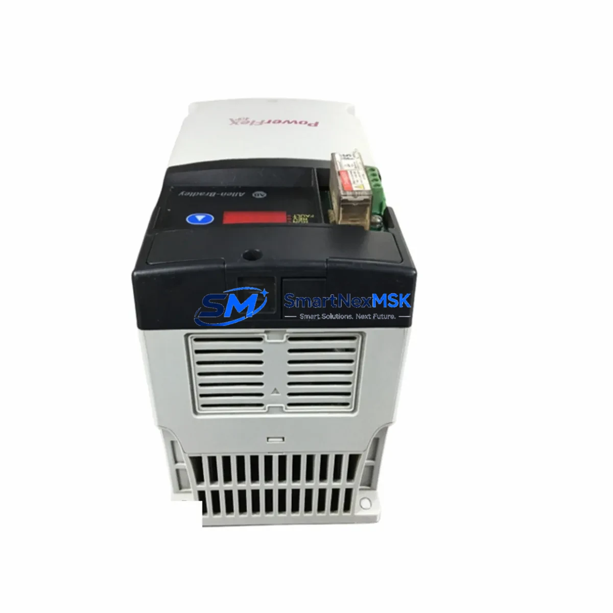
Allen-Bradley 22D-D1P4N104 Retrofit-Ready AC Drive for PowerFlex 4M Control Systems
The Allen-Bradley 22D-D1P4N104 is a 0.75kW (1HP), 200–240V single-phase input PowerFlex 4M AC drive engineered for seamless integration into legacy and modernized control architectures. Whether you are replacing a failed drive on an aging production line, upgrading a control cabinet from an obsolete VFD platform, or migrating a multi-axis system to a unified Rockwell Automation ecosystem, the 22D-D1P4N104 delivers the compatibility, reliability, and commissioning simplicity that industrial maintenance teams demand.
This unit supports the standard DSI (Drive Serial Interface) communication protocol, making it directly compatible with existing PowerFlex 4 and PowerFlex 4M network topologies without requiring gateway adapters or protocol converters. Engineers migrating from older Bulletin 160 or Bulletin 1305 drives will find the terminal layout and parameter structure familiar, significantly reducing re-commissioning time and the risk of wiring errors during cutover.
Upgrade Compatibility Table
| Attribute | Details |
|---|---|
| SKU / Part Number | 22D-D1P4N104 |
| Series | PowerFlex 4M |
| Power Rating | 0.75kW (1HP) |
| Input Voltage | 200–240V AC, 1-Phase |
| Output Voltage | 0–240V AC, 3-Phase |
| Output Current | 1.4A continuous |
| Communication | DSI (Drive Serial Interface); optional 22-COMM-E EtherNet/IP adapter |
| Enclosure Rating | IP20 / NEMA Type 1 |
| Mounting | DIN rail or panel mount |
| Direct Replacement For | PowerFlex 4 (22A-D1P4N104), Bulletin 160-AA02NSF1, Bulletin 1305-BA01A |
| Compatible Controllers | MicroLogix 1100, MicroLogix 1400, CompactLogix L1x/L2x, SLC 500 via AIC+ |
| HMI Compatibility | PanelView 800, PanelView Component C400/C600 |
| Commissioning Tool | Connected Components Workbench (CCW), DriveExplorer via 1203-USB |
| Retrofit Complexity | Low — terminal-for-terminal wiring match with PowerFlex 4 series |
| Warranty | 12 Months from date of shipment |
Retrofit Planning for Existing Automation Systems
A successful retrofit of the 22D-D1P4N104 into an existing control cabinet begins with a thorough audit of the power supply capacity. The drive draws up to 1.4A on the output side, but the upstream 24VDC control power rail — typically sourced from a 1606-XLP or similar Bulletin 1606 power supply — must be verified to support the DSI communication card and any connected I/O modules without voltage droop. In multi-drive panels, engineers should also confirm that the main circuit breaker and branch protection (commonly a 140M motor protection circuit breaker) are correctly rated for the aggregate inrush current during simultaneous drive startup.
Terminal wiring on the 22D-D1P4N104 follows the standard PowerFlex 4M layout: TB1 for power (R/L1, S/L2, T/L3 input; U/T1, V/T2, W/T3 output), TB2 for control terminals (digital inputs DI1–DI3, analog input AI, relay output, and 24VDC source). When replacing a Bulletin 1305 or older Bulletin 160 drive, the control terminal mapping must be cross-referenced carefully — particularly the enable input logic (active-high vs. active-low) and the analog reference scaling (0–10V vs. 4–20mA). Incorrect scaling will cause the motor to run at an unintended speed immediately upon energization, a common commissioning error that can be avoided by reviewing Parameter 42 (Speed Reference) and Parameter 46 (Analog Input Select) before the first run.
For systems using a 1747-AIC or 1761-NET-AIC Advanced Interface Converter to bridge the SLC 500 DH-485 network to the drive’s DSI port, the existing cable and adapter can typically be reused without modification. However, if the retrofit involves migrating the host controller from an SLC 500 to a CompactLogix L16ER or similar ControlLogix-family processor, the communication path should be redesigned to use a 22-COMM-E EtherNet/IP adapter mounted on the drive’s DSI port, enabling full parameter read/write and fault diagnostics over the plant Ethernet backbone. This eliminates the need for a dedicated DH-485 segment and simplifies the network topology considerably.
I/O expansion during the retrofit should also be planned in advance. If the new control scheme requires additional digital inputs beyond the three onboard DI terminals, a 1762-IQ8 or 1762-OW8 MicroLogix expansion module can be added to the host controller rack rather than overloading the drive’s onboard I/O. Similarly, if the application requires encoder feedback for closed-loop speed control, the 22D-D1P4N104 supports the optional 22-UTIL-P1 encoder feedback module, which mounts directly to the drive chassis without requiring a separate enclosure.
HMI screen migration is another critical step. Existing PanelView Component C400 or C600 screens configured for the legacy drive must have their tag databases updated to reflect the new drive’s parameter addresses. In most PowerFlex 4M applications, the core speed reference, run/stop command, and fault reset tags remain at the same Modbus register addresses as the PowerFlex 4, so screen migration is typically limited to updating the device address and verifying communication timeout settings. Full functional testing of all HMI screens — including fault display, speed setpoint entry, and jog functions — should be completed before returning the line to production.
Downtime Control During System Migration
Minimizing unplanned downtime during a drive replacement requires a structured pre-cutover checklist. Before removing the failed or obsolete unit, technicians should use DriveExplorer (via a 1203-USB programming cable) or Connected Components Workbench to export the full parameter file from the existing drive if it is still functional. This parameter backup — saved as a .dno or .ccwarc file — serves as the baseline for programming the replacement 22D-D1P4N104 and eliminates the need to reconstruct acceleration ramps, current limits, and fault response settings from memory or paper records.
The physical swap can typically be completed in under 30 minutes for a DIN-rail mounted unit: de-energize the panel, lock out / tag out per site LOTO procedures, photograph the existing terminal wiring, remove the old drive, mount the 22D-D1P4N104, reconnect terminals in sequence (power first, then control), and restore power. The drive’s onboard keypad provides immediate access to Parameter 01 (Output Frequency) and Parameter 02 (Output Current) for a quick sanity check before enabling the run command from the PLC.
To protect original program logic in the host controller — whether a MicroLogix 1400 or a CompactLogix L2x — the PLC program should be placed in Remote Program mode before the drive is de-energized. This prevents the controller from generating nuisance fault codes due to loss of drive communication during the swap window. Once the replacement drive is powered and communication is confirmed (DSI link LED solid green), the controller can be returned to Remote Run mode and the drive enabled through the normal start sequence. A 15-minute observation period under load, monitoring output current, DC bus voltage, and heatsink temperature via the drive’s diagnostic parameters, is recommended before declaring the retrofit complete.
Retrofit Support FAQ
Q1: Is the 22D-D1P4N104 a direct drop-in replacement for the PowerFlex 4 (22A-D1P4N104)?
Yes. The PowerFlex 4M shares the same terminal layout, parameter structure, and DSI communication interface as the PowerFlex 4. The primary difference is the 4M’s more compact form factor and enhanced EMC filtering. No wiring changes or PLC program modifications are required for a like-for-like swap.
Q2: Can I reuse my existing 1203-USB programming cable and DriveExplorer software?
Yes. The 1203-USB cable connects to the RJ45 DSI port on the 22D-D1P4N104 and is fully supported by DriveExplorer v7.x and Connected Components Workbench v13 or later. Ensure the USB driver is current before connecting to avoid enumeration errors on Windows 10/11 systems.
Q3: What wiring changes are needed when replacing a Bulletin 1305 drive with the 22D-D1P4N104?
The Bulletin 1305 uses a different control terminal numbering convention. A terminal cross-reference must be prepared before wiring. Key differences include the enable input (Terminal 1 on 1305 vs. DI1 on PowerFlex 4M) and the analog reference input (0–10V scaling may differ). Review the 22D-D1P4N104 User Manual (Publication 22D-UM001) and the 1305 migration guide before proceeding.
Q4: What does the 12-month warranty cover, and how is it processed?
All units supplied by SMARTNEXMSK carry a 12-month warranty from the date of shipment, covering manufacturing defects and functional failures under normal operating conditions. Each unit undergoes pre-shipment functional testing. Warranty claims are processed via email to [email protected] with the order reference and a description of the fault. Replacement units are dispatched within 3 business days of claim approval.
© 2026 SMARTNEXMSK. All rights reserved.
Original Source: https://smartnexmsk.com
Contact: [email protected] | +86 18259474341



