
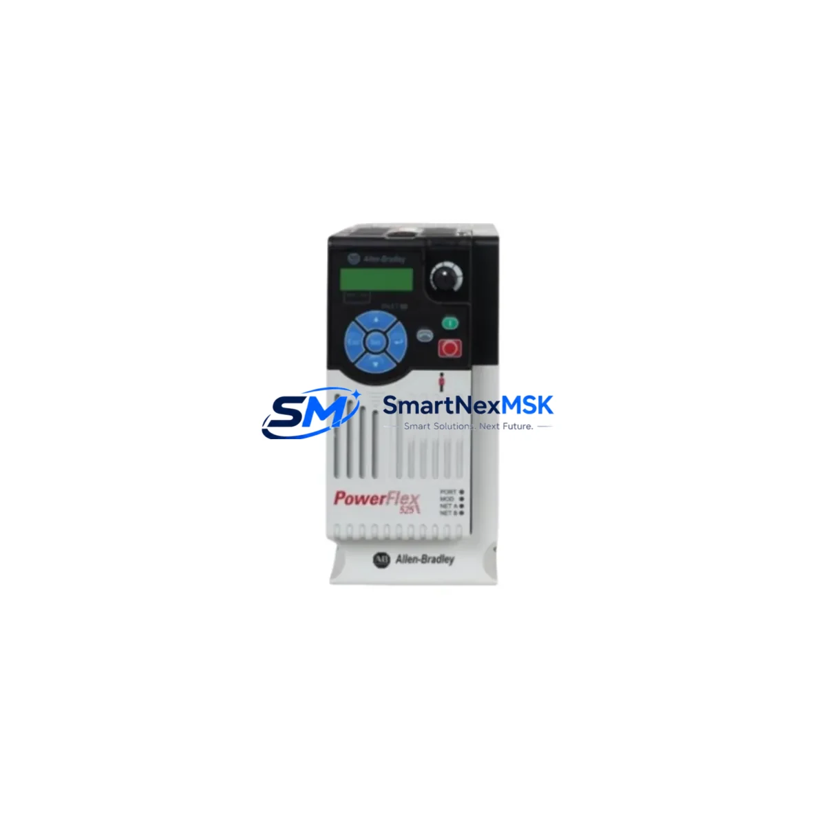
Allen-Bradley 25B-D010N104 Retrofit-Ready AC Drive for PowerFlex 525 Control Systems
The Allen-Bradley 25B-D010N104 is a 5 HP (3.7 kW), 480V three-phase AC variable frequency drive from the PowerFlex 525 series, engineered for seamless integration into existing automation architectures. Whether you are replacing an end-of-life drive on a legacy production line, upgrading a control cabinet from an older PowerFlex 4 or PowerFlex 40 platform, or migrating a distributed motion network to EtherNet/IP, the 25B-D010N104 delivers the compatibility, flexibility, and reliability that industrial retrofit projects demand. With a compact frame-B footprint, embedded EtherNet/IP adapter, and full support for the Studio 5000 / RSLogix 5000 programming environment, this drive is the preferred drop-in solution for system integrators and maintenance engineers working under tight downtime constraints.
Upgrade Compatibility Table
| Parameter | Details |
|---|---|
| SKU / Catalog Number | 25B-D010N104 |
| Series | PowerFlex 525 |
| Power Rating | 5 HP / 3.7 kW |
| Input Voltage | 480V AC, 3-Phase, 50/60 Hz |
| Output Current | 10.5 A |
| Frame Size | B (compact panel-mount) |
| Communication Protocol | Embedded EtherNet/IP (dual-port) |
| Control Interface | HIM (Human Interface Module) compatible; supports 25-HIM-A5 and 25-HIM-C2S |
| Replaces / Upgrades From | PowerFlex 4 (22A), PowerFlex 40 (22B), PowerFlex 400 (22C) |
| Backplane / Rack | Stand-alone (no rack required); DIN-rail or panel-mount |
| Terminal Wiring | Screw-type power terminals; compatible with standard AWG wiring from legacy installations |
| Programming Environment | Studio 5000 / RSLogix 5000; Connected Components Workbench (CCW) |
| Commissioning Tool | 1203-USB or 1784-U2DHP programming cable |
| Warranty | 12 Months from date of shipment |
| Condition | New / Surplus New / Tested Refurbished (specify at order) |
Retrofit Planning for Existing Automation Systems
Successful retrofit of the 25B-D010N104 into an existing control system begins well before the drive arrives on site. Engineers should start by auditing the existing power distribution panel to confirm that the upstream circuit breaker or fused disconnect — typically a 1492-FB or equivalent — is rated for the drive’s 10.5 A output current and that the incoming 480V supply is within the ±10% tolerance specified in the PowerFlex 525 user manual.
Terminal wiring compatibility is the next critical checkpoint. Legacy PowerFlex 4 (22A-D010N104) and PowerFlex 40 (22B-D010N104) installations typically use the same wire gauge and terminal layout, making the physical swap straightforward. However, engineers must verify that the 24 VDC control wiring to digital input terminals DI1–DI6 matches the new parameter assignments in the 25B series. If the legacy system used a 22-COMM-E EtherNet/IP adapter card on a PowerFlex 40, that external adapter is no longer required — the 25B-D010N104 includes a dual-port embedded EtherNet/IP interface, simplifying cabinet wiring and reducing the component count.
For installations migrating from DeviceNet (using a 22-COMM-D adapter) or RS-485 Modbus (using a 22-COMM-M adapter), a protocol migration step is required. The 25B-D010N104 natively supports EtherNet/IP; legacy DeviceNet nodes on the same network may need to be bridged through a 1788-EN2DN linking device or replaced with EtherNet/IP-native equivalents. During this migration, the ControlLogix or CompactLogix controller — for example, a 1756-L73 or 1769-L33ER — must have its I/O tree updated to reflect the new drive’s EtherNet/IP node address and electronic data sheet (EDS) file.
I/O expansion considerations are equally important. If the existing control cabinet uses a 1734 POINT I/O or 1769 Compact I/O rack to manage auxiliary motor control signals, engineers should confirm that the rack’s power supply module — such as the 1734-EP24DC or 1769-PA2 — has sufficient capacity to support any additional 24 VDC loads introduced during the upgrade. The 25B-D010N104’s onboard digital and analog I/O (two analog inputs, one analog output, six digital inputs, two digital outputs) can often absorb functions previously handled by discrete I/O modules, reducing overall panel complexity.
HMI screen updates are a frequently overlooked step. If the existing system uses a PanelView Plus 7 (2711P series) or a PanelView Component (2711C series), the drive faceplate or speed-reference display linked to the old drive tag must be remapped to the new 25B-D010N104 EtherNet/IP tag structure. Rockwell’s FactoryTalk View Studio makes this remapping straightforward, but it must be completed and tested in simulation before the physical cutover to avoid operator confusion during startup.
Finally, before energizing the replacement drive, engineers should upload and archive the original drive parameter file using DriveExecutive or the parameter backup function in Studio 5000. This ensures that acceleration ramps, PID tuning values, and fault response configurations from the legacy drive are preserved and can be restored or adapted to the new unit with minimal re-commissioning effort.
Downtime Control During System Migration
Minimizing production downtime during a drive replacement is the top priority for most plant maintenance teams. The 25B-D010N104 supports several strategies that make a rapid, controlled cutover possible.
First, pre-stage the replacement drive on the bench before the maintenance window begins. Download the backed-up parameter file from the legacy drive and load it into the 25B-D010N104 using Connected Components Workbench or a 25-HIM-A5 HIM module. Verify that all critical parameters — motor nameplate data, speed references, acceleration/deceleration ramps, and fault actions — are correctly transferred. This bench commissioning step can reduce on-site startup time from several hours to under 30 minutes.
Second, use the drive’s Safe Torque Off (STO) function to isolate the motor safely without removing main power from the cabinet. This allows technicians to swap the drive while adjacent equipment remains energized, protecting the integrity of the broader control system and avoiding a full panel shutdown.
Third, leverage the dual-port EtherNet/IP topology to maintain network continuity. The 25B-D010N104’s two Ethernet ports support a linear or ring (DLR — Device Level Ring) topology, meaning the network link to upstream and downstream devices is preserved even during the drive swap, provided the cable is re-routed through the new unit before the old one is removed.
Fourth, coordinate with the PLC programmer to implement a “drive not ready” interlock in the ControlLogix or CompactLogix ladder logic. This interlock holds the process in a safe, paused state — rather than triggering a fault or emergency stop — while the replacement drive initializes and establishes its EtherNet/IP connection. Once the drive reports “Ready” status on the network, the interlock releases and normal operation resumes automatically, keeping total controlled downtime to a minimum.
Retrofit Support FAQ
Q1: Is the 25B-D010N104 a direct drop-in replacement for the PowerFlex 40 22B-D010N104?
A: Mechanically and electrically, the 25B-D010N104 is highly compatible with the PowerFlex 40 22B-D010N104. The mounting footprint, power terminal layout, and control wiring are similar. The primary difference is the communication interface: the PowerFlex 525 uses embedded EtherNet/IP rather than the optional 22-COMM-E adapter card used on the PowerFlex 40. If your system currently uses EtherNet/IP, the adapter card can be removed and the embedded ports used directly. If your system uses DeviceNet or RS-485, a protocol migration step is required.
Q2: What commissioning steps are required after installing the 25B-D010N104?
A: After physical installation and wiring verification, connect to the drive using a 1203-USB programming cable or via EtherNet/IP from Studio 5000. Run the drive’s built-in motor auto-tune routine to optimize current and voltage regulation for your specific motor. Verify all digital input assignments, analog reference scaling, and fault response parameters. Perform a no-load test run before connecting the mechanical load, then a loaded test run at reduced speed before returning to full production speed.
Q3: How do I verify wiring compatibility before removing the old drive?
A: Document all existing terminal connections on the legacy drive using photographs and a wiring schedule. Cross-reference each terminal against the 25B-D010N104 wiring diagram in publication 520-UM001. Pay particular attention to the control terminal block (TB2): input common (COM), enable input, and analog reference terminals may have slightly different numbering between the PowerFlex 40 and PowerFlex 525 series. A side-by-side terminal comparison before the cutover eliminates the most common commissioning errors.
Q4: What does the 12-month warranty cover, and how is it claimed?
A: The 12-month warranty covers manufacturing defects, component failures under normal operating conditions, and functional non-conformance to the published specifications in the PowerFlex 525 user manual (publication 520-UM001). It does not cover damage resulting from incorrect installation, overvoltage events, or operation outside the rated environmental conditions. To initiate a warranty claim, contact [email protected] with the order number, serial number, and a description of the fault. Replacement or repair is typically processed within 5–10 business days, and return shipping for confirmed warranty cases is covered.
© 2026 SMARTNEXMSK. All rights reserved.
Original Source: https://smartnexmsk.com
Contact: [email protected] | +86 18259474341



