
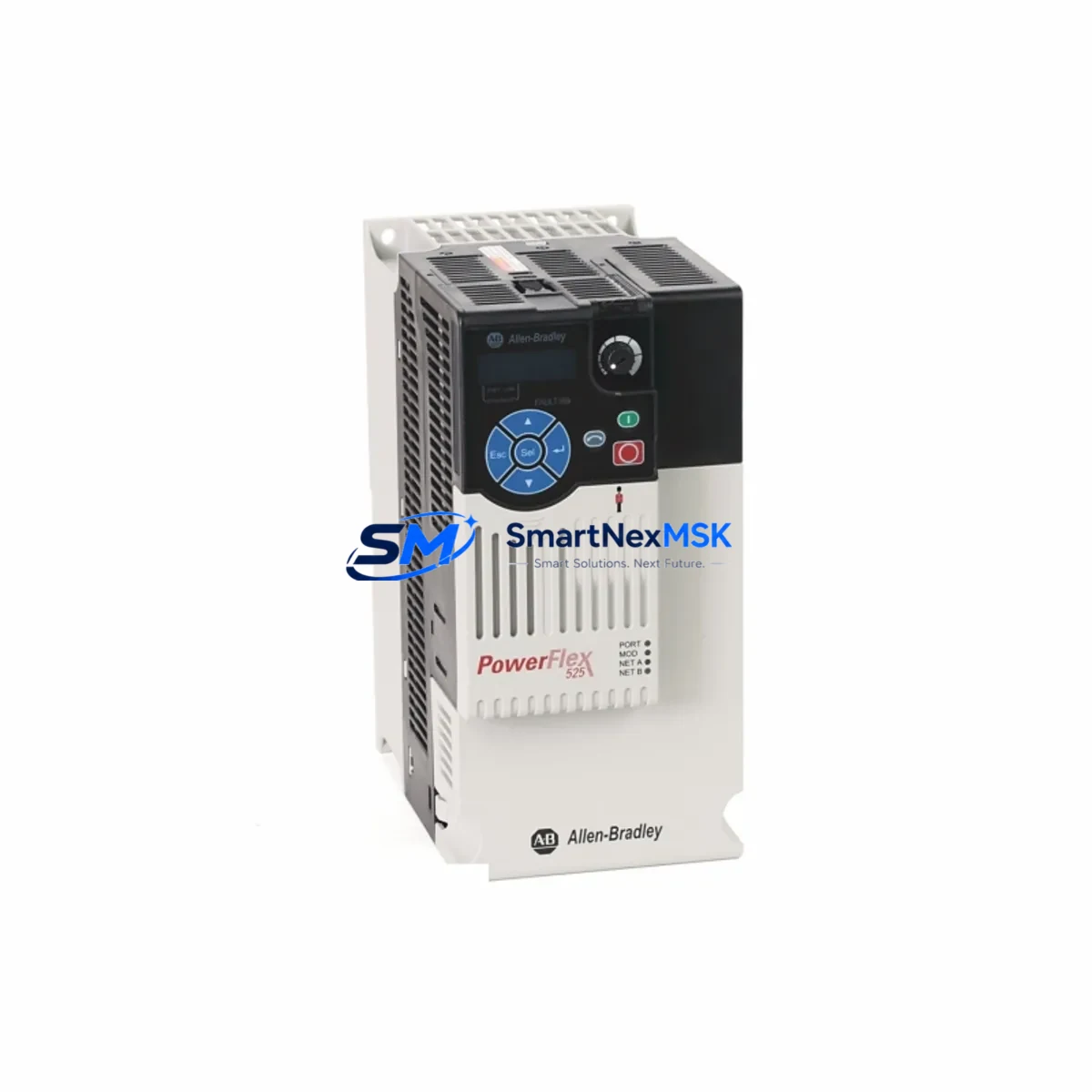
Allen-Bradley 25B-D013N104 Retrofit-Ready AC Drive for PowerFlex 525 Control Systems
The Allen-Bradley 25B-D013N104 is a 7.5 HP / 5.5 kW, 480V AC, three-phase variable frequency drive from the PowerFlex 525 series — one of Rockwell Automation’s most widely deployed compact drive platforms in industrial automation. Designed for seamless integration into existing control architectures, this unit is a direct retrofit solution for aging or discontinued PowerFlex 4, PowerFlex 4M, and early-generation PowerFlex 523 installations where the original hardware has reached end-of-life or is no longer available through standard distribution channels.
For maintenance engineers and system integrators managing legacy production lines, the 25B-D013N104 offers a critical advantage: it retains the same DIN-rail and panel-mount footprint as its predecessors, minimizing enclosure modifications during a control cabinet upgrade. The drive supports both EtherNet/IP and DSI (Drive Serial Interface) communication protocols, enabling direct integration with existing ControlLogix, CompactLogix, and MicroLogix controller platforms without requiring gateway hardware or protocol converters.
Before commissioning a replacement unit, field engineers should verify the following parameters against the existing installation: input power capacity (480V ±10%, 3-phase, 60 Hz), terminal block wiring gauge compatibility (typically 14–10 AWG for this frame size), backplane slot assignment if mounted in a multi-drive enclosure, and the drive node address configured in the original RSLogix 5000 or Studio 5000 program. If the legacy drive was communicating via a 20-COMM-E EtherNet/IP adapter or a 20-COMM-D DeviceNet adapter, confirm whether the 25B-D013N104’s onboard EtherNet/IP port can replace that adapter directly — in most cases it can, eliminating an additional hardware cost.
Program migration is a key concern during any PowerFlex retrofit. The 25B-D013N104 supports parameter backup and restore via the HIM (Human Interface Module) or through Connected Components Workbench (CCW) software. If the original drive parameters were stored on a 20-HIM-A6 or 20-HIM-C6S removable HIM module, those parameter sets can often be uploaded directly to the replacement unit, dramatically reducing commissioning time and the risk of parameter entry errors. Engineers should cross-reference parameter numbers between the legacy firmware version and the current 25B-D013N104 firmware to identify any renamed or restructured parameters before transfer.
In retrofit projects involving PowerFlex 4 or PowerFlex 4M drives, the terminal layout differences require attention. The 25B-D013N104 uses a standard PowerFlex 525 terminal arrangement: R/L1, S/L2, T/L3 for AC input; U/T1, V/T2, W/T3 for motor output; and a dedicated 24VDC control terminal block for digital I/O, analog inputs, and relay outputs. If the original installation used a PowerFlex 4 with a simplified 6-terminal layout, the field wiring will need to be re-terminated to match the expanded I/O terminal block of the 525 series. This is also an opportunity to add additional I/O points — the 25B-D013N104 supports up to 6 digital inputs, 2 digital outputs, 2 analog inputs, and 1 analog output, providing expanded control flexibility compared to earlier compact drive models.
For systems where the HMI panel was originally configured to communicate with a PowerFlex 4 via RS-485 Modbus RTU, the 25B-D013N104 supports Modbus RTU through its DSI port using a 25-COMM-M Modbus/TCP adapter or via the onboard EtherNet/IP interface. FactoryTalk View ME or SE screens referencing legacy drive tags will require tag remapping in the HMI project file, but the underlying drive parameter structure remains consistent enough that most standard speed reference, run/stop, and fault status tags can be remapped with minimal rework.
Supply chain continuity is a persistent challenge for facilities running legacy Rockwell Automation platforms. The 25B-D013N104 is stocked and available for immediate shipment, with full factory testing completed prior to dispatch. Each unit ships with a 12-month warranty covering manufacturing defects and component failures under normal operating conditions. For facilities managing critical uptime requirements, we recommend maintaining at least one spare unit on-site alongside related components such as the 25-RF027-AL EMC filter, 25-PM2-B2 brake resistor kit, and 25-COMM-E2P EtherNet/IP dual-port communication module to ensure rapid recovery in the event of an unplanned drive failure.
Upgrade Compatibility Table
| Parameter | Legacy (PowerFlex 4 / 4M) | 25B-D013N104 (PowerFlex 525) |
|---|---|---|
| Power Rating | 7.5 HP / 5.5 kW | 7.5 HP / 5.5 kW |
| Input Voltage | 480V AC, 3-Phase | 480V AC, 3-Phase (±10%) |
| Output Current | ~13A (varies by model) | 13.0A (Normal Duty) |
| Mounting | Panel / DIN Rail | Panel / DIN Rail (same footprint) |
| Communication | RS-485 DSI / DeviceNet (adapter) | EtherNet/IP (onboard) + DSI port |
| I/O Terminals | 6 DI / 1 DO / 1 AI | 6 DI / 2 DO / 2 AI / 1 AO |
| Programming Tool | RSLogix 500 / DriveExplorer | Studio 5000 / CCW / DriveExecutive |
| HIM Module | 20-HIM-A6 (optional) | 25-HIM-A8 / 25-HIM-C2S (optional) |
| Retrofit Recommendation | Direct replacement; re-terminate I/O wiring; remap HMI tags; verify node address | |
| Commissioning Focus | Parameter upload via HIM or CCW; verify accel/decel ramps, speed references, and fault responses | |
| Warranty | — | 12 Months (manufacturing defects) |
Retrofit Planning for Existing Automation Systems
A successful PowerFlex 525 retrofit begins well before the replacement unit arrives on-site. Start by auditing the existing control cabinet: document the current drive’s parameter list using DriveExplorer or a 20-HIM-A6 HIM module, photograph all terminal wiring, and record the drive’s node address and network configuration. If the cabinet also houses a 1769-L33ER CompactLogix controller or a 1756-L71 ControlLogix processor, confirm that the controller firmware is compatible with the Add-On Profile (AOP) for the PowerFlex 525 series before proceeding.
For multi-axis systems where the 25B-D013N104 shares a control enclosure with other drives — such as a PowerFlex 523 on a conveyor axis or a PowerFlex 527 on a servo-adjacent application — verify that the shared 24VDC control power supply (e.g., a 1606-XLP95E power supply) has sufficient capacity to support the additional I/O load introduced by the expanded terminal block. A 25-PM2-B2 dynamic braking resistor kit should be evaluated if the application involves high-inertia loads or frequent deceleration cycles.
Communication infrastructure planning is equally important. If the facility network uses a Stratix 5700 managed switch for EtherNet/IP device connectivity, assign a static IP address to the 25B-D013N104 before installation and update the controller’s I/O tree in Studio 5000 to reflect the new drive’s EDS file. For legacy DeviceNet installations using a 1788-EN2DN linking device, the migration to EtherNet/IP eliminates the need for the linking device entirely, simplifying the network topology and reducing potential points of failure. A 25-COMM-E2P dual-port EtherNet/IP module can be added if Device Level Ring (DLR) topology is required for high-availability applications.
Finally, ensure that any associated 25-RF027-AL EMC line filter is correctly rated for the installation environment and that the motor cable length does not exceed the drive’s maximum recommended cable distance without an output reactor. For installations with cable runs exceeding 50 meters, a 1321-3R series output reactor should be considered to protect motor insulation and reduce reflected wave voltage.
Downtime Control During System Migration
Minimizing production downtime during a drive replacement requires a structured changeover plan. The recommended approach is to pre-configure the 25B-D013N104 off-line using Connected Components Workbench (CCW) before the scheduled maintenance window. Load the parameter file exported from the legacy drive, adjust any firmware-version-specific parameters, and verify the configuration against the motor nameplate data and application requirements. This pre-staging step can reduce on-site commissioning time from several hours to under 30 minutes in most standard applications.
During the physical swap, label all control wiring before disconnection and use the terminal block wiring diagram from the 25B-D013N104 installation manual to guide re-termination. Power down the cabinet using the main disconnect, verify zero-energy state with a calibrated voltage tester, and remove the legacy drive. Install the 25B-D013N104 in the same panel position, re-terminate the power and control wiring, and restore the pre-staged parameter file via the 25-HIM-A8 HIM module or USB connection to a laptop running CCW.
Before returning the system to production, perform a no-load test run to verify rotation direction, speed reference response, and fault relay operation. Confirm that the ControlLogix or CompactLogix controller is communicating with the drive by checking the drive’s status tags in Studio 5000 — specifically the Drive Running, Drive Faulted, and Output Frequency tags. Once communication is confirmed, perform a loaded test run at reduced speed before returning to full production speed. Document the final parameter set and store a backup copy in the facility’s maintenance management system to support future troubleshooting and spare-parts planning.
Retrofit Support FAQ
Q: Is the 25B-D013N104 a direct drop-in replacement for a PowerFlex 4 22B-D013N104?
A: The 25B-D013N104 is functionally equivalent in power rating and voltage class, but it is not a pin-for-pin terminal replacement. The PowerFlex 525 series uses an expanded terminal block with additional I/O points compared to the PowerFlex 4. Control wiring will need to be re-terminated, and the parameter set will need to be re-entered or uploaded via HIM or CCW. The mounting footprint is similar but not identical — verify panel cutout dimensions before installation.
Q: Can I transfer parameters directly from my old drive to the 25B-D013N104?
A: If the legacy drive’s parameters were saved to a 20-HIM-A6 or 20-HIM-C6S HIM module, those files can be reviewed in DriveExplorer and manually cross-referenced to the 25B-D013N104 parameter list. Direct HIM-to-HIM transfer between PowerFlex 4 and PowerFlex 525 is not supported due to firmware architecture differences. Use Connected Components Workbench (CCW) to build the parameter file for the 525 series, referencing the legacy parameter printout as a guide.
Q: What communication options are available for integrating the 25B-D013N104 into an existing DeviceNet network?
A: The 25B-D013N104 does not include a native DeviceNet port. For DeviceNet integration, a 25-COMM-D DeviceNet adapter module can be installed in the drive’s peripheral port. Alternatively, this retrofit is an ideal opportunity to migrate the network segment to EtherNet/IP using the drive’s onboard port, which simplifies network management and eliminates the need for separate adapter hardware.
Q: What does the 12-month warranty cover, and what is the process for a warranty claim?
A: The 12-month warranty covers manufacturing defects and component failures under normal operating conditions, including rated voltage, current, and ambient temperature specifications. It does not cover damage resulting from incorrect installation, overvoltage events, or operation outside the drive’s rated parameters. To initiate a warranty claim, contact [email protected] with the unit serial number, purchase date, and a description of the fault condition. Replacement units are dispatched after fault verification, with full factory testing completed prior to shipment.
© 2026 SMARTNEXMSK. All rights reserved.
Original Source: https://smartnexmsk.com
Contact: [email protected] | +86 18259474341



