
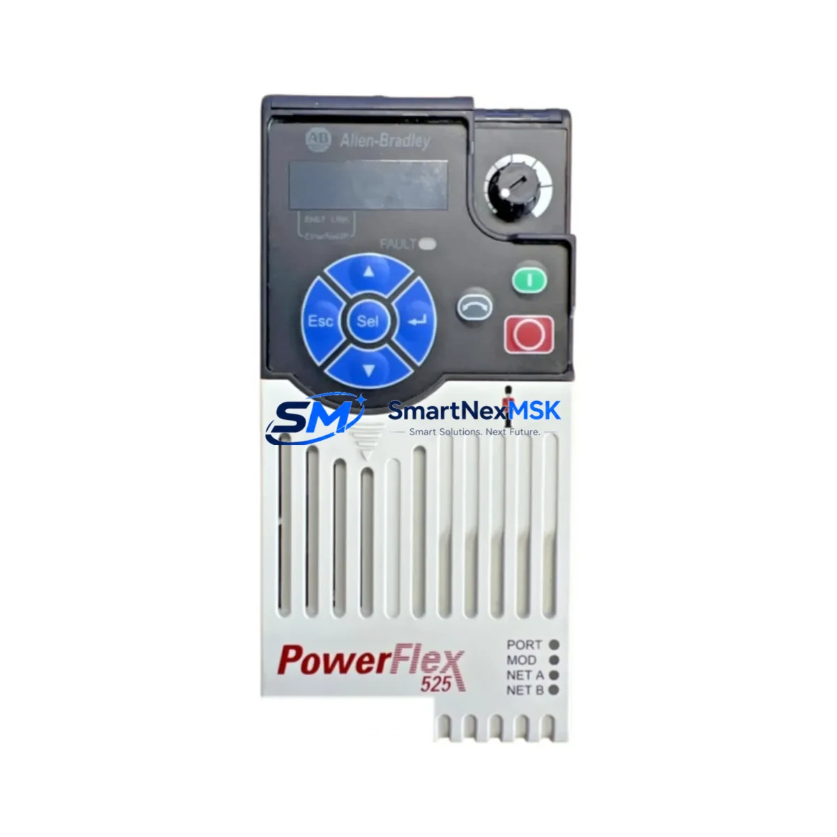
Allen-Bradley 25B-D6P0N104 Retrofit-Ready VFD for PowerFlex 523 Control Systems
The Allen-Bradley 25B-D6P0N104 is a 2.2 kW (3 HP), 480 V AC, three-phase variable frequency drive from the PowerFlex 523 series — one of Rockwell Automation’s most widely deployed compact drive platforms in industrial automation. Designed for smooth motor speed control in conveyor systems, pump stations, HVAC applications, and general-purpose machine automation, this drive is a proven retrofit solution for aging PowerFlex 4, PowerFlex 40, and PowerFlex 400 installations that require a modern, protocol-compatible replacement without full panel redesign.
For facilities managing legacy control architectures, the 25B-D6P0N104 offers a direct upgrade path that preserves existing wiring infrastructure, reduces engineering rework, and minimizes production downtime. Its compact footprint and standard DIN-rail or panel-mount installation make it compatible with most existing control cabinet layouts, including those originally designed around older Bulletin 160 or Bulletin 1305 drives.
Upgrade Compatibility Table
| Parameter | Details |
|---|---|
| SKU / Part Number | 25B-D6P0N104 |
| Series | PowerFlex 523 |
| Power Rating | 2.2 kW / 3 HP |
| Input Voltage | 480 V AC, 3-Phase |
| Output Current | 6.0 A |
| Communication | EtherNet/IP (via 25-COMM-E2P option), DSI port standard |
| Control Interface | Integral LCD keypad; compatible with 25-HIM-A5 and 25-HIM-C2S remote HIM panels |
| Installation | Panel mount; IP20 enclosure rating |
| Common Replacements | PowerFlex 4 (22A), PowerFlex 40 (22B), Bulletin 160, Bulletin 1305 |
| Retrofit Recommendation | Verify terminal block pitch and wire gauge before re-termination; TB1 layout differs from 22B series |
| Commissioning Note | Re-enter motor nameplate data; verify P031–P035 parameters; test at low speed before full-load run |
| Warranty | 12 Months — covers manufacturing defects, functional failure under normal operating conditions |
Retrofit Planning for Existing Automation Systems
Successful integration of the 25B-D6P0N104 into an existing control system requires a structured pre-installation review. Begin by auditing the existing panel’s power supply capacity — confirm that the 24 VDC control power rail, typically sourced from a 1606-XLP or similar Bulletin 1606 power supply, can support the drive’s logic and I/O requirements alongside other panel loads such as safety relays, PLC I/O modules, and HMI backlight circuits.
Terminal block compatibility is a critical checkpoint. The PowerFlex 523 uses a different TB1 terminal layout compared to the PowerFlex 40 (22B series), so existing field wiring for analog speed reference (0–10 V or 4–20 mA), digital inputs (Run Forward, Run Reverse, Fault Reset), and relay outputs must be re-mapped accordingly. Use the drive’s built-in I/O configuration parameters to reassign functions without requiring additional wiring changes where possible.
If the existing system uses a ControlLogix or CompactLogix controller — such as a 1756-L71 or 1769-L33ER — communicating over EtherNet/IP, the 25-COMM-E2P communication adapter must be installed in the drive’s peripheral expansion slot. This enables full CIP messaging, drive parameter read/write via MSG instructions, and integration with Studio 5000 Logix Designer for online monitoring. For legacy DeviceNet-based systems using a 1747-SDN scanner on an SLC 500 rack, a protocol gateway or migration to EtherNet/IP at the network level should be planned as part of the broader upgrade scope.
Backplane and rack considerations apply when the drive is part of a larger motion or I/O expansion architecture. Verify that the 1756 chassis or 1769 CompactLogix local bus has sufficient slots and power budget if additional 1769-IQ16 digital input modules, 1769-OF4 analog output modules, or 1769-ASCII communication modules are being added as part of the same retrofit project. Address assignment for the new drive must be confirmed in the PLC program — update the drive’s node address and verify that all AOI (Add-On Instructions) or explicit MSG blocks reference the correct IP address or device tag.
HMI screen updates are often overlooked during drive replacements. If the facility uses a PanelView Plus 7 or PanelView 800 terminal, verify that all drive status tags — including drive fault codes, output frequency, and motor current — are correctly mapped to the new drive’s parameter addresses. The PowerFlex 523 uses a different parameter numbering scheme than the PowerFlex 40, so tag remapping in FactoryTalk View Studio or Connected Components Workbench may be required before go-live.
Downtime Control During System Migration
Minimizing production interruption during a drive retrofit requires a parallel preparation strategy. Before the scheduled maintenance window, pre-configure the replacement 25B-D6P0N104 on a bench using the 25-HIM-A5 handheld HIM or Connected Components Workbench software. Upload the parameter file from the outgoing drive if it is still functional, or reconstruct the parameter set from the original commissioning documentation. Key parameters to pre-load include motor nameplate data (P031–P035), acceleration/deceleration ramps (A141–A142), speed reference source selection, and digital I/O assignments.
During the cutover window, follow a structured swap sequence: isolate and lock out the incoming power, document all field wiring terminations with photographs before removal, install the new drive, re-terminate field wiring per the 25B-D6P0N104 wiring diagram, restore power, and perform a no-load jog test before reconnecting the motor. This sequence protects the original program logic in the PLC — no changes to the controller program are required if the drive’s EtherNet/IP node address and parameter mapping are pre-configured to match the outgoing unit.
For critical continuous-process applications, consider staging a hot-standby spare drive pre-configured with identical parameters. This reduces mean time to repair (MTTR) in the event of an unexpected drive fault, and is consistent with best practices for high-availability automation systems. All units supplied by SMARTNEXMSK are pre-tested under load conditions prior to shipment, with a full functional test report available upon request.
Retrofit Support FAQ
Q1: Is the 25B-D6P0N104 a direct drop-in replacement for the PowerFlex 40 (22B-D6P0N104)?
A: The power rating and voltage class are equivalent, but the terminal block layout and parameter structure differ between the PowerFlex 40 and PowerFlex 523 series. Field wiring re-termination and parameter re-entry are required. The drive is not plug-compatible without wiring adaptation.
Q2: What communication options are supported for PLC integration?
A: The 25B-D6P0N104 includes a standard DSI port for local HIM connection. EtherNet/IP connectivity requires the 25-COMM-E2P peripheral adapter. DeviceNet and PROFIBUS options are available via 25-COMM-D and 25-COMM-P adapters respectively, supporting migration from legacy fieldbus architectures.
Q3: How is the drive commissioned after installation?
A: Use the integral LCD keypad or Connected Components Workbench to enter motor nameplate data, configure I/O assignments, and set speed reference source. Perform a static motor test (parameter t062) before running under load. Verify output frequency and current readings against motor specifications before returning the system to production.
Q4: What does the 12-month warranty cover?
A: The 12-month warranty covers manufacturing defects and functional failure under normal operating conditions from the date of shipment. It includes free replacement or repair of confirmed defective units. Damage caused by incorrect installation, overvoltage, or environmental conditions outside the drive’s rated specifications is excluded. All units are functionally tested prior to dispatch.
© 2026 SMARTNEXMSK. All rights reserved.
Original Source: https://smartnexmsk.com
Contact: [email protected] | +86 18259474341



