
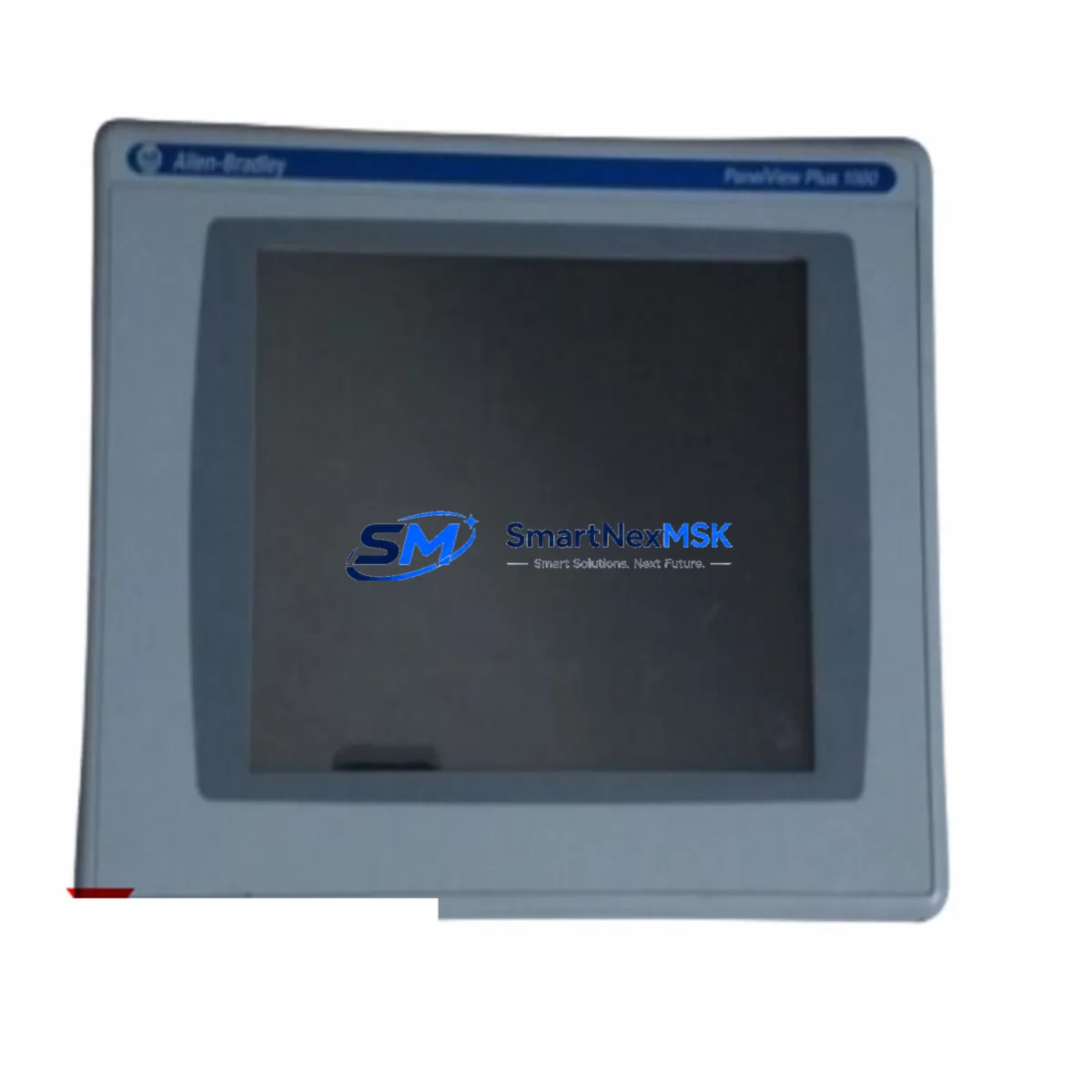
Allen-Bradley 2711P-T10C4D8 Retrofit-Ready HMI for PanelView Plus 7 Control Systems
The Allen-Bradley 2711P-T10C4D8 is a 10.4-inch color touch terminal from the PanelView Plus 7 Standard series, engineered to serve as a direct retrofit replacement for aging PanelView Plus 6 and PanelView Plus 6 Mobile terminals across a wide range of industrial control applications. Whether your facility is managing a legacy ControlLogix 5561 or CompactLogix L32E-based control cabinet, or migrating from an older SLC 500 or MicroLogix 1400 platform via a gateway bridge, the 2711P-T10C4D8 provides a validated upgrade path that minimizes engineering rework and preserves existing HMI screen logic wherever possible.
Designed for demanding industrial environments, this terminal supports EtherNet/IP as its primary communication protocol, enabling seamless integration with Logix 5000-family controllers including the ControlLogix 5580, CompactLogix 5380, and GuardLogix 5580 safety controllers. The unit operates on 24 VDC nominal power, drawing approximately 1.5 A under full load, and mounts into a standard NEMA 4/4X panel cutout — making it physically compatible with most existing enclosure layouts without requiring panel modification.
Upgrade Compatibility Table
| Parameter | 2711P-T10C4D8 (This Unit) | Predecessor: 2711P-T10C4A8 |
|---|---|---|
| Display Size | 10.4″ Color TFT LCD | 10.4″ Color TFT LCD |
| Communication | EtherNet/IP (dual-port) | EtherNet/IP (single-port) |
| Power Supply | 24 VDC, ~1.5 A | 24 VDC, ~1.4 A |
| Panel Cutout | Standard NEMA 4/4X | Standard NEMA 4/4X |
| OS Platform | Windows CE 6.0 / FactoryTalk View ME | Windows CE 6.0 / FactoryTalk View ME |
| FactoryTalk View ME Version | v8.x and above recommended | v6.x – v8.x |
| Replacement Recommendation | Direct drop-in for 2711P-T10C4A8 and 2711P-T10C4D6 | — |
| Commissioning Note | Verify IP address, tag database, and alarm configuration after swap | — |
| Warranty | 12 Months | — |
Retrofit Planning for Existing Automation Systems
When integrating the 2711P-T10C4D8 into an existing control cabinet, the retrofit process typically begins with a power budget review. The terminal requires a stable 24 VDC supply, and engineers should verify that the existing 1606-XLP power supply or equivalent unit has sufficient residual capacity after accounting for all connected I/O modules, relay outputs, and communication adapters. In many legacy panels, the original power supply was sized tightly around the previous HMI’s draw, so a capacity audit before installation prevents nuisance trips during commissioning.
Terminal block wiring is generally straightforward for this replacement. The 2711P-T10C4D8 uses a standard 24 VDC two-wire power connection at the rear of the unit. If the existing panel uses a 1492-IFM interface module or similar terminal block arrangement for signal routing, no rewiring of the control circuit is typically required — only the HMI power leads need to be confirmed and reconnected. Engineers should label all wires before disconnecting the old terminal and photograph the existing wiring layout for reference during reassembly.
Backplane and rack considerations are not applicable to this terminal, as the 2711P-T10C4D8 is a standalone panel-mount HMI rather than a rack-mounted module. However, if the control system includes a 1756 ControlLogix chassis with a 1756-EN2T or 1756-EN2TR EtherNet/IP communication module, the HMI connects to the same Ethernet segment and communicates directly with the controller over the plant network. Engineers should confirm that the Ethernet switch port connected to the HMI supports the required bandwidth and that no VLAN segmentation blocks EtherNet/IP traffic between the terminal and the controller.
Module addressing and tag database migration are among the most time-sensitive steps in any HMI retrofit. The 2711P-T10C4D8 runs FactoryTalk View Machine Edition (ME), and existing .MER application files from a PanelView Plus 6 terminal can typically be opened and converted using FactoryTalk View Studio ME v8.x or later. Engineers should audit all tag references, particularly any that point to legacy SLC 500 or PLC-5 data files via a 1761-NET-ENI or 1783-ETAP Ethernet adapter, and verify that the tag paths resolve correctly after conversion. Alarm configurations, trend displays, and recipe data tables should be validated individually before the terminal goes live.
For facilities running a mixed communication environment — for example, a ControlLogix controller communicating upstream via a 1756-DNB DeviceNet bridge to legacy field devices, while the HMI connects via EtherNet/IP — the 2711P-T10C4D8 handles the Ethernet side cleanly. The DeviceNet and other fieldbus segments remain transparent to the HMI as long as the controller’s tag database correctly maps all I/O data. No additional protocol conversion hardware is required at the HMI level.
I/O expansion modules such as the 1769-IQ16 digital input module or 1769-OB16 digital output module connected to a CompactLogix rack are unaffected by the HMI swap, as all I/O data is managed at the controller level and surfaced to the HMI through the tag database. This architecture means the retrofit scope is cleanly limited to the HMI terminal itself, the Ethernet cable, and the FactoryTalk View ME application file — reducing both risk and downtime.
Downtime Control During System Migration
Minimizing production downtime during an HMI retrofit requires a structured pre-commissioning approach. Before the scheduled maintenance window, engineers should prepare a fully configured and tested replacement terminal offline using FactoryTalk View Studio ME. The .MER application file should be loaded onto the 2711P-T10C4D8, the IP address pre-configured to match the outgoing terminal, and all screen navigation and alarm acknowledgment sequences verified on a bench setup connected to a test controller or simulator.
During the actual swap, the sequence should follow a defined checklist: power down the panel, disconnect the old terminal’s power and Ethernet leads, remove the unit from the cutout, install the 2711P-T10C4D8, reconnect power and Ethernet, and power up. Because the IP address and application file are pre-loaded, the terminal should establish communication with the ControlLogix or CompactLogix controller within seconds of power-up. Engineers should confirm that all process values are displaying correctly, that alarm states match the controller’s current fault register, and that any operator setpoint screens are reading and writing values as expected before releasing the panel back to production.
For critical processes where even a brief interruption is unacceptable, a shadow commissioning approach is recommended: install the new terminal in a temporary location on the panel door, connect it to the same Ethernet segment as the existing HMI, and run both terminals simultaneously for a validation period before removing the old unit. This approach preserves full operator visibility throughout the transition and allows the maintenance team to identify any tag mapping discrepancies without affecting process control. The 2711P-T10C4D8’s dual-port Ethernet switch capability further simplifies network topology during this parallel-run phase.
Retrofit Support FAQ
Q: Is the 2711P-T10C4D8 a direct replacement for the 2711P-T10C4A8 and 2711P-T10C4D6?
A: Yes. The 2711P-T10C4D8 is physically and functionally compatible with both models. The panel cutout dimensions are identical, the power requirements are equivalent, and the FactoryTalk View ME application files from the predecessor units can be converted and loaded without rebuilding screens from scratch. Minor tag path adjustments may be required if the original application referenced legacy controller data files.
Q: What commissioning steps are required after installation?
A: After physical installation, verify the terminal’s IP address matches the network plan, confirm EtherNet/IP communication is established with the target controller (ControlLogix, CompactLogix, or GuardLogix), validate all tag references in the FactoryTalk View ME application, and cycle through all operator screens to confirm display accuracy. Alarm configurations and recipe tables should be tested under simulated process conditions before returning the system to automatic operation.
Q: Does the unit ship pre-tested?
A: Yes. Every 2711P-T10C4D8 unit is powered on and functionally tested prior to shipment. Display, touch calibration, Ethernet port operation, and firmware version are verified. Units are packed with anti-static protection and shipped with tracking. A test report is available upon request.
Q: What does the 12-month warranty cover?
A: The 12-month warranty covers hardware defects in materials and workmanship under normal operating conditions. It includes free replacement or repair of the unit if a manufacturing defect is identified within the warranty period. Physical damage caused by incorrect installation, overvoltage, or environmental exposure beyond the unit’s rated specifications is not covered. Warranty claims are processed within 5 business days of receipt of the returned unit.
© 2026 SMARTNEXMSK. All rights reserved.
Original Source: https://smartnexmsk.com
Contact: [email protected] | +86 18259474341



