
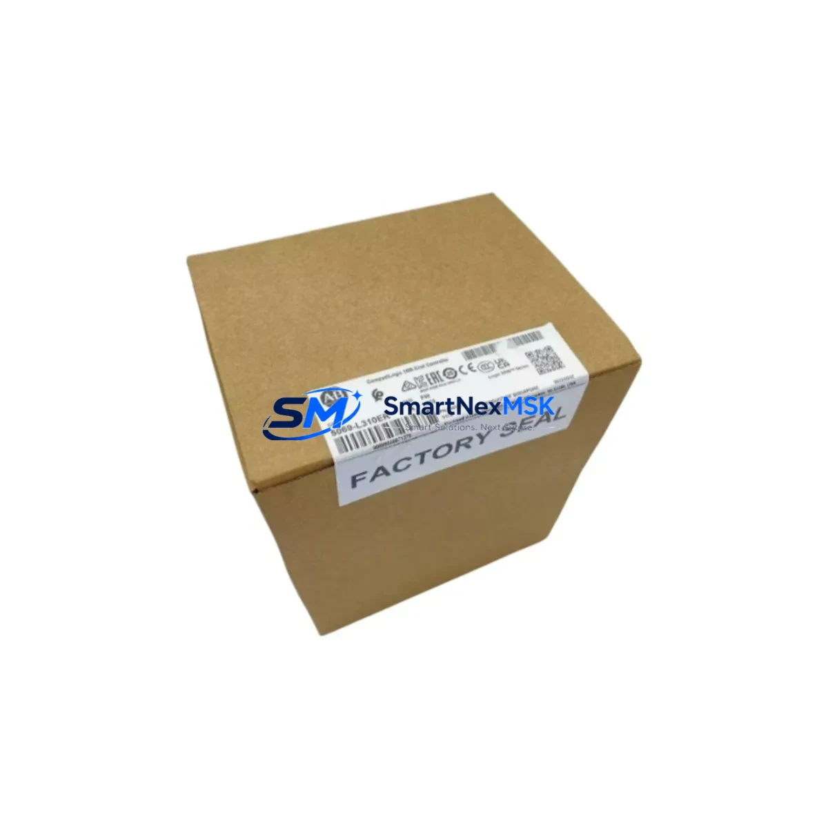
Allen-Bradley 5069-L3 100ERM Spare for CompactLogix 5380 Automation
The Allen-Bradley 5069-L3 100ERM is a maintenance-critical spare part for Rockwell Automation’s CompactLogix 5380 Programmable Automation Controller (PAC) platform. With 1MB of user memory and integrated Dual-Port EtherNet/IP connectivity, this controller is widely deployed across discrete manufacturing, process control, and material handling systems. When a 5069-L3 100ERM fails or reaches end-of-service life, the impact on production continuity is immediate. Holding a verified, tested replacement unit in your spare parts inventory is the most effective strategy for minimizing unplanned downtime and protecting your automation investment.
This unit is sourced as an original Allen-Bradley component, inspected, and tested prior to shipment. It is backed by a 12-month warranty covering manufacturing defects and functional performance. Whether you are managing a planned maintenance window, responding to an emergency fault, or building out a strategic spare parts buffer for aging CompactLogix infrastructure, this 5069-L3 100ERM is ready for immediate deployment.
Spare Maintenance Table
| Parameter | Specification |
|---|---|
| Part Number / SKU | 5069-L3 100ERM |
| Brand | Allen-Bradley (Rockwell Automation) |
| Series | CompactLogix 5380 |
| Product Type | Programmable Automation Controller (PAC) |
| User Memory | 1 MB |
| Communication Ports | Dual-Port EtherNet/IP (embedded switch) |
| I/O Capacity | Up to 16 local I/O modules (5069 Compact I/O) |
| Power Supply Compatibility | 5069-PA4, 5069-PB4 (24VDC bus) |
| Backplane Compatibility | 5069 Compact I/O backplane |
| Operating Temperature | 0°C to 60°C (32°F to 140°F) |
| Mounting | DIN rail or panel mount |
| Origin | United States |
| Condition | Original, tested before shipment |
| Warranty | 12 Months |
| Compatibility | CompactLogix 5380 family; Studio 5000 Logix Designer |
| Maintenance Recommendation | Replace every 7–10 years or upon first fault indication; inspect firmware version before swap |
Maintenance Planning for Continuous Operation
Replacing a 5069-L3 100ERM in a live production environment requires a structured approach that goes beyond swapping the controller. Maintenance engineers should treat this event as a full control-cabinet audit. Before powering down, verify that the 5069-PA4 or 5069-PB4 power supply module is delivering stable 24VDC bus voltage — a marginal power supply is a common root cause of controller faults and should be replaced concurrently if it shows any signs of ripple or thermal stress.
Inspect all 5069 Compact I/O modules seated on the local backplane. Digital input modules (such as the 5069-IB16) and digital output modules (such as the 5069-OB16) should be checked for loose terminal connections, discolored wiring, and correct LED status. Analog I/O modules used for process signal conditioning — including 4–20mA loops — should be verified against their calibration records. Any module showing intermittent faults should be flagged for replacement during the same maintenance window.
EtherNet/IP network integrity is critical for the 5069-L3 100ERM’s dual-port embedded switch. Inspect the Ethernet patch cables and managed switches in the control cabinet for port errors, duplex mismatches, and cable continuity. If the system uses a 1783-series Stratix managed switch, review its port diagnostics before restoring the controller to service. Communication faults that appear after a controller swap are frequently caused by pre-existing network infrastructure issues rather than the replacement unit itself.
For systems that include safety or relay output circuits, inspect the 700-series Allen-Bradley safety relays and any associated 1492-series terminal blocks for contact wear and proper torque on screw terminals. Signal isolation barriers — particularly those protecting analog inputs from high-voltage interference — should be tested for correct output scaling. If the cabinet includes an Allen-Bradley PanelView Plus HMI, verify that the EtherNet/IP connection to the new controller is re-established and that all tag bindings are intact after the firmware restore.
For older CompactLogix installations being extended beyond their original design life, consider stocking a 1756-EN2T EtherNet/IP communication module or equivalent as a bridge component if the system architecture requires integration with legacy ControlLogix backplanes. Fuse holders and 1492-GH fuse blocks within the same panel should also be inspected and replaced if they show signs of heat discoloration or intermittent continuity.
Site Replacement Workflow
Step 1 — Pre-replacement preparation: Export the current controller program using Studio 5000 Logix Designer. Save the .ACD project file and document the firmware revision currently running on the 5069-L3 100ERM. Confirm that the replacement unit’s firmware is compatible or upgrade it offline before installation.
Step 2 — Safe isolation: Follow your site’s lockout/tagout (LOTO) procedure. De-energize the 5069 power supply and confirm zero-energy state on all I/O circuits before removing the controller from the backplane.
Step 3 — Physical swap: Remove the faulty 5069-L3 100ERM from the DIN rail or panel mount. Seat the replacement unit firmly onto the backplane connector. Reconnect EtherNet/IP cables to both ports as required by your network topology (linear, ring, or star).
Step 4 — Program restore and commissioning: Download the saved .ACD project to the replacement controller. Verify all I/O module connections are recognized in the I/O tree. Perform a controlled test run before returning the system to automatic production mode.
Step 5 — Documentation: Update your maintenance log with the replacement date, firmware version, and any observations noted during the swap. This record supports future planned maintenance intervals and warranty claims.
Spare Parts Support FAQ
Q: Is this 5069-L3 100ERM compatible with my existing CompactLogix 5380 backplane and I/O modules?
A: Yes. The 5069-L3 100ERM is designed for the CompactLogix 5380 platform and is compatible with all 5069 Compact I/O modules and the 5069-PA4/PB4 power supplies. Confirm your Studio 5000 project firmware version and match it to the replacement unit before installation.
Q: What testing is performed before shipment?
A: Each unit undergoes functional power-on testing and visual inspection prior to dispatch. The controller is verified to initialize correctly and communicate over EtherNet/IP. A test report is available upon request for critical applications.
Q: How should I manage spare parts inventory for aging CompactLogix 5380 systems?
A: Industry best practice for critical automation lines is to hold a minimum of one controller spare per production line, supplemented by spares for high-wear components such as power supply modules and I/O modules. For systems with 5+ years of service, a proactive replacement cycle of 7–10 years is recommended for the controller itself.
Q: What does the 12-month warranty cover?
A: The warranty covers manufacturing defects and functional failures under normal operating conditions for 12 months from the date of shipment. It does not cover damage resulting from incorrect installation, overvoltage events, or physical mishandling. Warranty claims are processed promptly with advance replacement options available for critical downtime situations.
© 2026 SMARTNEXMSK. All rights reserved.
Original Source: https://smartnexmsk.com
Contact: [email protected] | +86 18259474341



