
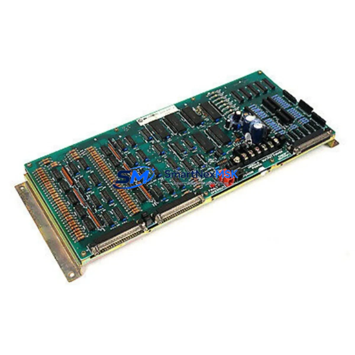
Allen-Bradley 8500-HDIO Retrofit-Ready High-Density Digital I/O for PLC-5 Control Systems
The Allen-Bradley 8500-HDIO is a high-density digital I/O module engineered for the PLC-5 control platform — one of Rockwell Automation’s most widely deployed legacy architectures in process manufacturing, material handling, and discrete automation. As the PLC-5 family has reached end-of-life status, the 8500-HDIO has become a critical retrofit and replacement component for facilities that must maintain operational continuity without committing to a full ControlLogix or CompactLogix migration. SMARTNEXMSK maintains verified stock of the 8500-HDIO, fully tested and backed by a 12-month warranty, ready for immediate dispatch to support planned upgrades and emergency line recoveries.
Upgrade Compatibility Table
| Parameter | Details |
|---|---|
| Module SKU | 8500-HDIO |
| Compatible Platform | Allen-Bradley PLC-5 Series (5/10, 5/12, 5/15, 5/20, 5/25, 5/30, 5/40, 5/60, 5/80) |
| Backplane Interface | PLC-5 Universal Remote I/O (RIO) backplane; 1771-series rack compatible |
| I/O Density | High-density digital; confirm point count and voltage rating against original wiring schedule |
| Communication Compatibility | Data Highway Plus (DH+), Remote I/O (RIO) — verify node address before installation |
| Installation Requirement | 1771-series rack slot; verify slot addressing and chassis keying |
| Replacement Recommendation | Direct drop-in for same-SKU failed or end-of-life units; confirm firmware revision compatibility with RSLogix 5 project file |
| Commissioning Focus | Module address configuration, I/O map verification in RSLogix 5, terminal block re-termination, and force-test of all I/O points |
| Warranty | 12 months from date of shipment; covers manufacturing defects and functional failure under normal operating conditions |
Retrofit Planning for Existing Automation Systems
Replacing the 8500-HDIO in an active PLC-5 installation requires a structured approach that accounts for the full scope of the control architecture. Before removing the failed module, engineers should document the existing I/O map from the RSLogix 5 project file, noting the slot number, rack address, and I/O image table assignments that the 8500-HDIO occupies. Any mismatch in module addressing after replacement will cause the processor to fault on I/O configuration errors at startup.
The 1771-series chassis that houses the 8500-HDIO must be inspected for backplane integrity. Corrosion on the backplane connector or damaged rack guides can cause intermittent communication faults that are often misdiagnosed as module failure. If the chassis is a 1771-A1B, 1771-A2B, or 1771-A4B rack, verify that the power supply — typically a 1771-P4S or 1771-P6S — can support the additional current draw of the replacement module, particularly in high-density configurations where multiple I/O modules share a single power rail.
Terminal block wiring is a common source of commissioning delays. The 8500-HDIO uses a removable terminal block that should be transferred from the failed unit to the replacement module without re-terminating individual conductors where possible. If the terminal block shows signs of heat damage or loose terminations, replace it with a compatible 1771-series terminal block assembly and re-terminate from the original wiring schedule. Label each conductor before removal to prevent cross-wiring errors during reinstallation.
For systems that also rely on analog signal conditioning, the 8500-HDIO retrofit is often performed alongside replacement of 1771-IFE or 1771-OFE analog I/O modules that share the same rack. Similarly, if the control system includes a 1771-SDN DeviceNet Scanner or a 1771-KF2 Data Highway Plus communication module, verify that these modules remain online during the I/O replacement to avoid losing network visibility to field devices such as PowerFlex drives or PanelView HMI terminals.
In systems where the PLC-5 processor communicates with a PanelView 1000 or PanelView 1400 HMI over DH+, the I/O replacement should be coordinated with a review of the HMI tag database. If the 8500-HDIO replacement changes any I/O image table addresses — even temporarily — HMI screens that reference those addresses may display incorrect status until the project is re-synchronized. Where possible, perform the module swap during a scheduled maintenance window and validate all HMI displays against the physical I/O state before returning the line to production.
For facilities planning a longer-term migration from PLC-5 to ControlLogix, the 8500-HDIO replacement can serve as a bridge solution while the migration project is scoped. Rockwell Automation’s migration tools support conversion of RSLogix 5 project files to Studio 5000 Logix Designer format, but the I/O configuration must be remapped to 1756-series ControlLogix I/O modules. In this context, maintaining a working PLC-5 system with a verified 8500-HDIO allows production to continue uninterrupted while the new ControlLogix chassis, 1756-L8x processor, and 1756-IB16 or 1756-OB16 digital I/O modules are configured and tested offline.
Downtime Control During System Migration
Minimizing unplanned downtime during an 8500-HDIO replacement begins with pre-staging the replacement module before the maintenance window opens. SMARTNEXMSK ships the 8500-HDIO with a functional test report confirming that all I/O points have been verified under load conditions. This allows the maintenance team to confirm module integrity before the line is taken offline, reducing the risk of discovering a secondary fault during the replacement window.
The PLC-5 processor should be placed in Program mode before the module is removed. This suspends I/O scanning and prevents the processor from generating fault codes that could trigger safety interlocks or alarm annunciators in the control room. If the system uses a 1771-ASB Remote I/O Adapter to extend I/O to a remote rack, verify that the remote rack remains in a safe state during the local rack maintenance — particularly if the remote rack controls actuators or drives that could respond to a loss of I/O communication.
After the replacement module is seated and the terminal block is reconnected, perform a controlled power cycle of the rack before returning the processor to Run mode. Use RSLogix 5 to force-test each I/O point on the 8500-HDIO against the physical field device — confirming that inputs respond correctly to field signals and that outputs drive their respective loads without unexpected behavior. Document the test results and retain them as part of the maintenance record for the installation. Once all points are verified, return the processor to Run mode and monitor the first production cycle for any anomalies in the I/O image table before releasing the line to full production speed.
Retrofit Support FAQ
Q: Is the 8500-HDIO a direct replacement for the original module in my PLC-5 rack?
A: Yes, the 8500-HDIO is a same-SKU replacement that installs into the same 1771-series rack slot as the original module. No hardware modifications are required. Verify that the module address switches are set to match the original configuration before powering the rack.
Q: What commissioning steps are required after installing the replacement 8500-HDIO?
A: After installation, place the PLC-5 processor in Program mode, seat the module, reconnect the terminal block, and perform a rack power cycle. Use RSLogix 5 to verify the I/O configuration, force-test all digital points, and confirm that the I/O image table reflects the correct field device states before returning to Run mode.
Q: How do I verify wiring compatibility between the replacement module and my existing terminal block?
A: The 8500-HDIO uses a standard 1771-series removable terminal block. Transfer the existing terminal block from the failed module to the replacement unit where possible. If re-termination is required, reference the original wiring schedule and verify conductor labeling before removal. Confirm input voltage ratings and output current ratings match the field device specifications.
Q: What does the 12-month warranty cover, and how is it claimed?
A: The 12-month warranty covers manufacturing defects and functional failure under normal operating conditions from the date of shipment. To initiate a warranty claim, contact SMARTNEXMSK at [email protected] with the order reference, module serial number, and a description of the fault. Replacement or repair will be arranged within the warranty period at no additional cost.
© 2026 SMARTNEXMSK. All rights reserved.
Original Source: https://smartnexmsk.com
Contact: [email protected] | +86 18259474341



