
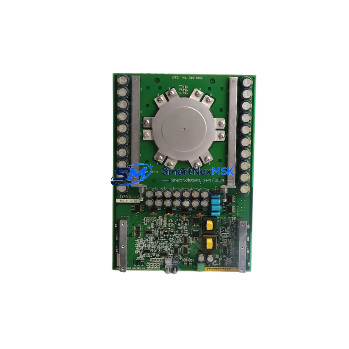
Allen-Bradley GU-D08 80173-109-01 Retrofit-Ready SGCT Gate Driver for PowerFlex MV Control Systems
The Allen-Bradley GU-D08 80173-109-01 (also referenced as FGC800B-130DS) is a Symmetrical Gate Commutated Thyristor (SGCT) gate driver module engineered for medium-voltage variable frequency drive applications within the PowerFlex MV drive platform. As legacy PowerFlex MV installations age and original spare parts become increasingly scarce, this module serves as a verified retrofit-ready replacement that enables plant engineers to restore full drive functionality without redesigning the control architecture or replacing the entire drive cabinet.
Whether you are managing a planned upgrade cycle, responding to an unplanned drive fault, or executing a broader control system modernization program, the GU-D08 80173-109-01 provides a direct-fit solution that preserves your existing wiring, backplane connections, and PLC program logic — minimizing engineering rework and reducing total downtime exposure.
Upgrade Compatibility Table
| Parameter | Details |
|---|---|
| Part Number | GU-D08 / 80173-109-01 / FGC800B-130DS |
| Compatible Platform | Allen-Bradley PowerFlex MV (Medium Voltage) Drive Series |
| Module Function | SGCT Gate Driver — controls firing of Symmetrical Gate Commutated Thyristors in the inverter power stack |
| Interface / Backplane | Direct plug-in to PowerFlex MV inverter chassis backplane; no adapter required |
| Communication Compatibility | Compatible with existing PowerFlex MV control fiber-optic gate signal links; no protocol reconfiguration required |
| Installation Requirement | Observe ESD precautions; verify DC bus is fully discharged before module swap; torque terminal screws to OEM specification |
| Replacement Recommendation | Replace as matched set per inverter phase leg where possible; individual module replacement is supported for fault isolation |
| Commissioning Focus | Verify gate signal integrity via drive diagnostic software (e.g., DriveExecutive or Studio 5000 Logix Designer); confirm SGCT firing sequence before re-energizing |
| Warranty | 12-Month Warranty — covers manufacturing defects and functional failure under normal operating conditions |
Retrofit Planning for Existing Automation Systems
A successful retrofit of the GU-D08 80173-109-01 into an aging PowerFlex MV installation requires a structured pre-replacement assessment. Before removing the faulty gate driver, engineers should document the current drive configuration using the existing Human Machine Interface (HMI) panel — typically a PanelView Plus terminal connected to the drive’s control network — and export any drive parameter files via DriveExecutive or Connected Components Workbench to ensure the configuration can be restored exactly after the module swap.
The PowerFlex MV drive chassis houses multiple functional boards in addition to the SGCT gate driver. The Main Control Board (MCB) manages overall drive logic and communicates with the plant’s ControlLogix or CompactLogix PLC via an EtherNet/IP or ControlNet adapter module. The Power Interface Board (PIB) coordinates signals between the control section and the power stack. When replacing the GU-D08, it is important to confirm that the PIB and MCB firmware versions are compatible with the replacement gate driver revision — mismatched firmware can cause nuisance faults or prevent the drive from completing its self-test sequence.
On the power side, the SGCT devices themselves — typically mounted on the inverter heat sink assembly — must be inspected for signs of thermal stress or gate lead damage before the new gate driver is installed. If the SGCT devices show degradation, replacing the gate driver alone will not resolve the underlying fault. In such cases, a coordinated replacement of both the gate driver module and the affected SGCT devices is recommended to restore full drive reliability.
For plants running older ControlNet-based architectures, the retrofit may also involve verifying the integrity of the 1786-RPA/B ControlNet repeater links and the 1784-PCIC programming cable connections used during commissioning. If the site has migrated or is planning to migrate to EtherNet/IP, the 20-COMM-E EtherNet/IP adapter installed in the drive’s peripheral slot should be confirmed as compatible with the updated network topology before the drive is returned to service.
I/O expansion requirements should also be reviewed during the retrofit window. If the plant’s control system relies on 1756-IB16 or 1756-OB16 digital I/O modules in the ControlLogix chassis to interface with the drive’s auxiliary contacts and status outputs, verify that the I/O module firmware and the Logix program’s I/O tree configuration match the physical rack layout. Any changes to the drive’s fault relay wiring or auxiliary output assignments must be reflected in the PLC program before the drive is re-enabled.
Finally, confirm that the 24 VDC control power supply feeding the gate driver’s logic circuits is within specification. Voltage sags or ripple on the control power rail are a common root cause of intermittent gate driver faults in aging drive cabinets, and addressing control power quality before installing the replacement module will significantly improve long-term reliability.
Downtime Control During System Migration
Minimizing production downtime during a PowerFlex MV gate driver replacement requires careful sequencing of isolation, replacement, and recommissioning steps. Begin by coordinating with the operations team to schedule the replacement during a planned maintenance window, and ensure that a complete drive parameter backup — including all application-specific tuning values, speed references, and fault response configurations — has been saved to a laptop running DriveExecutive or to the drive’s internal memory card if equipped.
Once the drive is safely isolated and the DC bus voltage has been confirmed at zero using a calibrated high-voltage meter, the GU-D08 80173-109-01 can be removed and the replacement module installed. The fiber-optic gate signal cables connecting the gate driver to the SGCT devices should be handled carefully to avoid contaminating the optical connectors — even minor contamination can cause intermittent gate signal loss and unpredictable drive behavior after restart.
After physical installation, restore the drive parameters from the saved backup before initiating the drive’s self-test routine. Use the drive’s built-in diagnostic functions to verify that all SGCT gate channels are responding correctly and that no new fault codes are present. If the drive is connected to a ControlLogix system via EtherNet/IP, confirm that the drive’s node address and network configuration are intact and that the PLC’s MSG instructions are communicating successfully before releasing the drive to automatic control.
For critical production lines where even a brief unplanned stop is unacceptable, consider maintaining a pre-tested spare GU-D08 80173-109-01 module on-site as part of a structured critical spare parts program. A pre-tested spare — verified on a test bench or during a previous planned outage — can reduce the active replacement window to under two hours, preserving production continuity and protecting the plant’s OEE targets.
Retrofit Support FAQ
Q1: Is the GU-D08 80173-109-01 a direct drop-in replacement for the original Allen-Bradley gate driver in my PowerFlex MV drive?
Yes. The GU-D08 80173-109-01 / FGC800B-130DS is designed as a direct-fit replacement for the original gate driver module in compatible PowerFlex MV drive chassis. No mechanical modifications or wiring changes are required. Confirm the drive’s chassis revision and MCB firmware version against the module’s compatibility data sheet before installation to ensure full functional equivalence.
Q2: What commissioning steps are required after installing the replacement gate driver?
After installation, restore the drive’s saved parameter file, then run the drive’s built-in SGCT gate test routine via the HMI or DriveExecutive software. Verify that all gate channels report healthy status and that no fault codes are active. Perform a no-load test run at low speed before returning the drive to full production load. Document all commissioning results for your maintenance records.
Q3: How do I verify wiring and terminal compatibility before replacing the module?
Refer to the PowerFlex MV drive’s wiring diagram (available in the drive’s installation manual, publication 7000-IN007) to confirm the gate driver’s fiber-optic connector assignments and control power terminal designations. Compare the replacement module’s connector layout against the original before disconnecting any cables. Label all fiber-optic cables with their channel assignments before removal to prevent misconnection during reinstallation.
Q4: What does the 12-month warranty cover, and what is the process for a warranty claim?
The 12-month warranty covers manufacturing defects and functional failures under normal operating and storage conditions. It does not cover damage resulting from incorrect installation, overvoltage events, or physical mishandling. To initiate a warranty claim, contact our sales team with the module’s serial number, a description of the fault symptom, and your original purchase documentation. Replacement or repair will be arranged promptly to minimize your system downtime.
© 2026 SMARTNEXMSK. All rights reserved.
Original Source: https://smartnexmsk.com
Contact: [email protected] | +86 18259474341



