
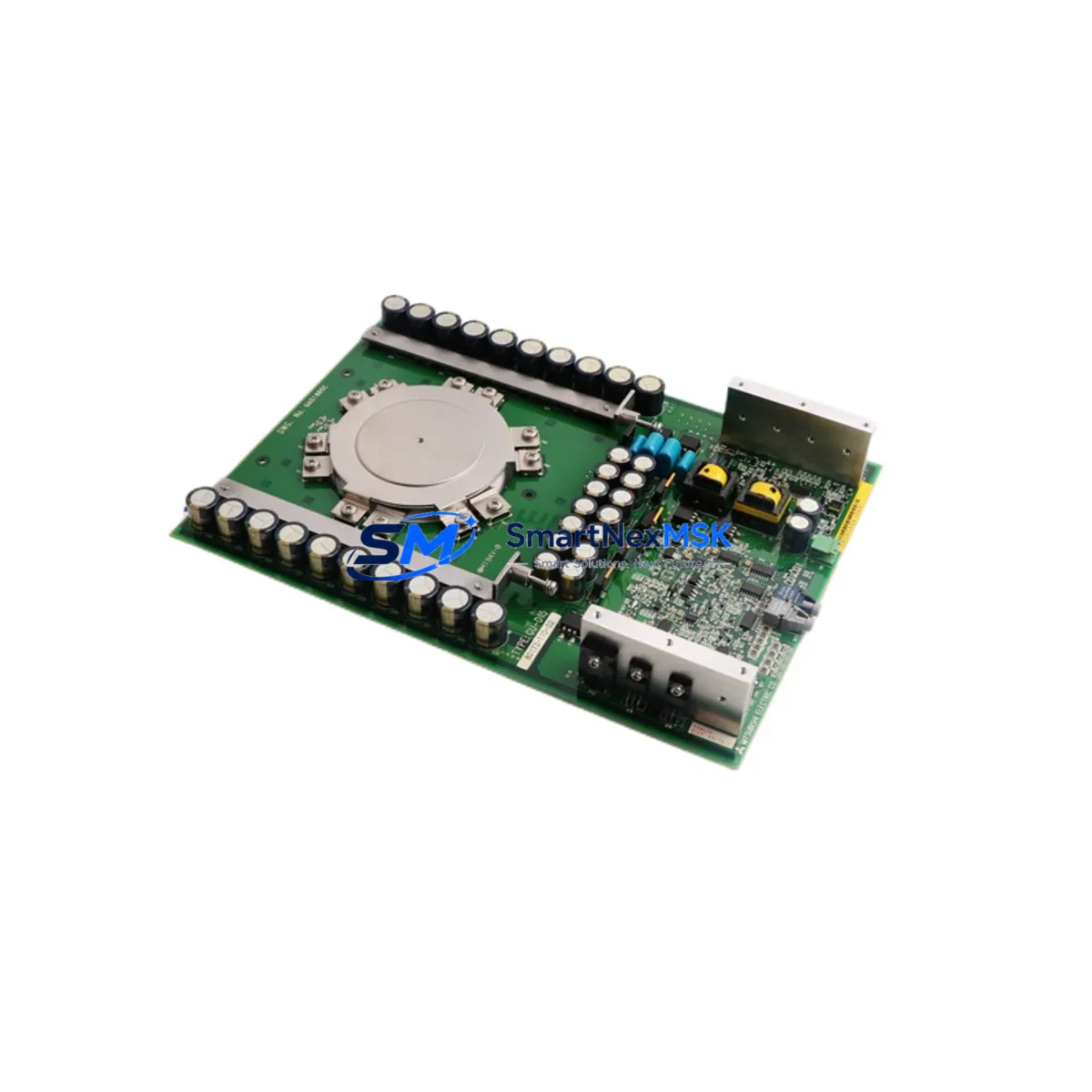
Allen-Bradley GU-D15 80173-110-02 Retrofit-Ready Thyristor for PowerFlex Control Systems
The Allen-Bradley GU-D15 80173-110-02 G651885C is a GCT thyristor power module engineered for high-reliability performance in industrial drive and motion control applications. As legacy PowerFlex drive systems age and original components reach end-of-life, this module serves as a proven retrofit solution — enabling engineers and maintenance teams to restore full drive functionality without replacing the entire control cabinet or migrating to a new control platform.
Whether you are managing a planned upgrade cycle or responding to an unplanned drive failure, the GU-D15 80173-110-02 G651885C provides a direct-fit replacement path that preserves your existing wiring topology, backplane interface, and control logic. This module is sourced from verified supply channels, undergoes pre-shipment functional testing, and is backed by a 12-month warranty covering manufacturing defects and operational failures under normal industrial conditions.
Upgrade Compatibility Table
| Parameter | Details |
|---|---|
| SKU / Part Number | GU-D15 80173-110-02 G651885C |
| Brand / Manufacturer | Allen-Bradley (Rockwell Automation) |
| Module Type | GCT Thyristor Power Module |
| Compatible Series | PowerFlex 700, PowerFlex 400, 1336 PLUS II Drive Systems |
| Interface / Backplane | Direct plug-in to existing drive power stack; no backplane adapter required |
| Terminal Wiring | Matches OEM terminal layout; verify gate drive connector orientation before installation |
| Communication Compatibility | Transparent to drive firmware; no protocol reconfiguration required |
| Installation Requirement | Torque gate terminals to spec; verify snubber circuit integrity post-installation |
| Commissioning Note | Run drive self-test and verify firing angle calibration after module swap |
| Replacement Recommendation | Replace in matched pairs where drive topology requires symmetrical thyristor stacks |
| Warranty | 12 Months — covers manufacturing defects and operational failure under normal use |
Retrofit Planning for Existing Automation Systems
Retrofitting a thyristor power module in an active production environment requires careful pre-work to avoid extended downtime and protect the integrity of the surrounding control system. Before removing the failed GU-D15 80173-110-02 G651885C, technicians should document the existing wiring configuration, photograph terminal connections, and record the drive’s parameter set using RSLogix 5000 or DriveExecutive software. This ensures that the replacement module can be commissioned against a verified baseline.
In a typical PowerFlex 700 or 1336 PLUS II retrofit scenario, the thyristor module sits within the power stack alongside the drive’s DC bus capacitor bank, gate driver board, and rectifier bridge assembly. When the GU-D15 fails, it is common to also inspect the associated snubber resistors and capacitors, as these components absorb switching transients and often degrade in parallel with the thyristor. Replacing the snubber network at the same time as the GU-D15 80173-110-02 G651885C reduces the risk of repeat failures.
For systems where the PowerFlex drive communicates over DeviceNet or EtherNet/IP using a 20-COMM-D or 20-COMM-E communication adapter, the retrofit process is transparent at the network layer — no node address changes or EDS file updates are required. The drive will resume normal communication once power is restored and the self-test sequence completes successfully.
In multi-drive control cabinets, it is advisable to verify the 24VDC control power supply — such as the 1606-XLP or similar Allen-Bradley power supply module — is within specification before energizing the retrofitted drive. Undervoltage on the control rail can cause erratic gate firing and may damage the new thyristor module during initial startup. Similarly, confirm that the 1492-IFM I/O interface modules connected to the drive’s digital I/O terminals are correctly mapped in the PLC program before resuming automatic operation.
Where the control system includes a PanelView Plus HMI terminal, verify that the drive status tags and fault code displays are functioning correctly after the retrofit. In some installations, drive fault history stored in the HMI’s tag database may need to be cleared to prevent false alarm conditions from appearing on the operator screen. If the system uses a ControlLogix or CompactLogix controller as the supervisory PLC, confirm that the Add-On Instruction (AOI) for the drive is still correctly linked to the physical I/O map after the module replacement.
For older installations using a 1336 PLUS II drive with a 1336-GM1 or 1336-BRF brake resistor module, ensure that the dynamic braking circuit is tested independently after the thyristor swap, as braking performance is directly dependent on the firing characteristics of the new GU-D15 80173-110-02 G651885C module. A controlled deceleration test under partial load is recommended before returning the machine to full production speed.
Downtime Control During System Migration
Minimizing unplanned downtime during a thyristor module replacement is a primary concern for maintenance engineers managing continuous production lines. The GU-D15 80173-110-02 G651885C is designed to support a rapid swap procedure — with proper preparation, an experienced technician can complete the physical replacement in under two hours, including isolation, module exchange, torque verification, and initial power-on testing.
To protect the original program logic during the retrofit, upload the drive parameter file to a laptop running DriveExecutive or Connected Components Workbench before de-energizing the drive. Store this file alongside the PLC program backup from the ControlLogix or CompactLogix controller. If the drive is configured with a custom parameter set — including acceleration ramps, current limits, and fault response behaviors — these values must be restored to the replacement module before the drive is returned to automatic mode.
For facilities operating on a 24/7 production schedule, it is advisable to pre-stage the GU-D15 80173-110-02 G651885C replacement module in the maintenance store before a failure occurs. Having a verified spare on the shelf eliminates procurement lead time from the critical path and allows the maintenance team to respond to a drive fault within a single shift. Our in-stock inventory and same-day dispatch capability supports this just-in-time spare parts strategy.
After the module is installed and the drive is re-energized, perform a no-load run test to verify that the output voltage waveform is symmetrical and that the drive is not generating nuisance fault codes. Follow this with a stepped load test — bringing the motor to 25%, 50%, 75%, and 100% of rated load — while monitoring drive current, heatsink temperature, and DC bus voltage. This structured commissioning sequence confirms that the GU-D15 80173-110-02 G651885C is operating correctly and that the surrounding power stack components are in good condition before full production resumes.
Retrofit Support FAQ
Q: Is the GU-D15 80173-110-02 G651885C a direct drop-in replacement for the original Allen-Bradley thyristor module?
A: Yes. The GU-D15 80173-110-02 G651885C is a form-fit-function replacement for the original OEM module. It uses the same terminal layout, backplane interface, and electrical ratings, allowing installation without modifications to the existing wiring or drive housing.
Q: What commissioning steps are required after installing the replacement module?
A: After installation, restore the drive parameter file, run the drive self-test sequence, verify gate firing calibration, and perform a stepped load test from no-load to full rated current. Confirm that all fault codes are cleared and that the HMI displays correct drive status before returning to automatic operation.
Q: How do I verify wiring compatibility before installation?
A: Compare the terminal diagram of the GU-D15 80173-110-02 G651885C against the existing wiring documentation for your drive. Pay particular attention to gate drive connector polarity, snubber circuit connections, and any auxiliary feedback wiring. If the original wiring documentation is unavailable, photograph all connections before removal.
Q: What does the 12-month warranty cover?
A: The 12-month warranty covers manufacturing defects and operational failures under normal industrial operating conditions. It does not cover damage resulting from incorrect installation, overvoltage events, or operation outside the module’s rated electrical parameters. Our technical team is available to support commissioning and troubleshooting throughout the warranty period.
© 2026 SMARTNEXMSK. All rights reserved.
Original Source: https://smartnexmsk.com
Contact: [email protected] | +86 18259474341



