
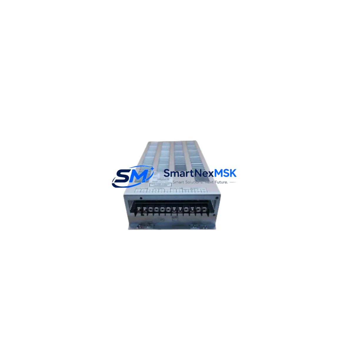
Allen-Bradley HBC65-Q7594 Spare for HBC65 Automation: Spare Replacement & Industrial Downtime Risk Control
The Allen-Bradley HBC65-Q7594 (part number 80026-088-01) is an original industrial power supply module engineered for the HBC65 series automation platform. In continuous-process and discrete manufacturing environments, an unplanned power supply failure can cascade into full line shutdowns within minutes. Stocking a verified, tested HBC65-Q7594 spare eliminates that risk and restores system availability without waiting on extended lead times from distribution channels.
This unit is sourced as an original Allen-Bradley component, inspected prior to shipment, and backed by a 12-month warranty covering manufacturing defects and functional performance. It is suitable for maintenance engineers managing aging HBC65-series control cabinets, as well as procurement engineers building strategic spare parts inventories for long-term system support.
Spare Maintenance Table
| Parameter | Specification / Detail |
|---|---|
| Part Number (SKU) | HBC65-Q7594 / 80026-088-01 |
| Brand | Allen-Bradley (Rockwell Automation) |
| Series | HBC65 |
| Product Type | Industrial Power Supply Module |
| Compatibility | HBC65-series automation and control systems |
| Origin | United States (OEM) |
| Weight | 530 g |
| Application Environment | Industrial control cabinets, automation panels, PLC/DCS power rails |
| Installation | Direct drop-in replacement for HBC65-Q7594 / 80026-088-01 |
| Maintenance Recommendation | Inspect input/output wiring, verify rail voltage, check downstream I/O modules before energizing |
| Warranty | 12 Months — covers manufacturing defects and functional performance |
| Pre-shipment Testing | Functional verification performed before dispatch |
| Shipping | Fast global shipping; export documentation available |
Maintenance Planning for Continuous Operation
When replacing the HBC65-Q7594 power supply in a live control cabinet, a disciplined maintenance workflow significantly reduces re-commissioning time and prevents secondary failures. Maintenance engineers should treat this replacement as an opportunity to inspect the full power distribution chain within the enclosure.
Before energizing the new unit, verify the incoming AC supply voltage and confirm that the upstream circuit breaker or fused disconnect is rated correctly for the HBC65 platform. Inspect the DC output bus and check for voltage drop across the power rail — degraded rail voltage is a common cause of erratic behavior in connected 1756-series I/O modules or ControlLogix processor cards sharing the same backplane. If the cabinet includes a 1756-PA75 or 1756-PB75 power supply on a ControlLogix chassis, cross-check its output as well, since a failing HBC65 supply can mask or be masked by a degraded chassis power supply.
Examine all terminal blocks and wiring connections at the power supply input and output terminals. Loose or corroded terminals are a leading cause of intermittent power faults in industrial environments. If the cabinet uses Phoenix Contact or Weidmüller terminal strips, inspect for discoloration or heat damage that may indicate prior overcurrent events.
Check any 24 VDC relay coils and solid-state relay (SSR) modules powered from the HBC65 supply output. A failing power supply often causes relay chatter or false trips before complete failure — if relay modules such as Allen-Bradley 700-series or equivalent third-party units show signs of contact wear, replace them concurrently to avoid a repeat callout.
If the system includes a 1769-SDN DeviceNet scanner or a 1756-ENBT EtherNet/IP communication module, confirm that communication is restored and stable after power-up. Communication modules are sensitive to supply voltage transients during startup. Similarly, if an operator interface such as a PanelView Plus 6 or PanelView 800 HMI is powered from the same distribution circuit, verify its startup sequence and confirm no alarm states are latched from the prior fault event.
For systems with signal isolators or loop-powered 4–20 mA transmitters connected to analog I/O modules, verify signal integrity after the power supply swap. A brief power interruption can shift zero references on some older transmitter models. Fuse holders on the 24 VDC distribution rail should also be inspected — replace any fuses that show signs of thermal stress, and document the replacement in the maintenance log for future reference.
Site Replacement Workflow
Step 1 — Isolation: De-energize the control cabinet following your site LOTO (Lockout/Tagout) procedure. Confirm zero energy state at the power supply input terminals using a calibrated multimeter.
Step 2 — Documentation: Photograph the existing wiring and label all connections before disconnecting. Record the existing unit’s part number and revision level for your maintenance records.
Step 3 — Removal: Disconnect input and output wiring in sequence. Remove the HBC65-Q7594 from its mounting position — note any DIN rail clips or panel fasteners specific to the HBC65 enclosure design.
Step 4 — Installation: Mount the replacement HBC65-Q7594 (80026-088-01) and reconnect all wiring per the original documentation. Torque terminal screws to the manufacturer’s specification to ensure reliable contact.
Step 5 — Verification: Before full system energization, perform a point-to-point continuity check on all reconnected circuits. Energize the supply and measure output voltage under no-load, then under normal operating load. Confirm output is within specification before releasing the system to production.
Step 6 — System Restore: Restore all downstream devices in sequence — I/O modules, communication modules, HMI, and field devices. Monitor the first 15 minutes of operation for any anomalies. Update the CMMS (Computerized Maintenance Management System) with the replacement record, including the new unit’s serial number and warranty expiry date.
This structured approach minimizes total downtime, ensures system compatibility is maintained, and creates a traceable maintenance record that supports future audits and spare parts planning.
Spare Parts Support FAQ
Q1: Is the HBC65-Q7594 (80026-088-01) a direct drop-in replacement for the original unit?
Yes. The replacement unit carries the same part number and revision specification as the original Allen-Bradley HBC65-Q7594 / 80026-088-01. It is a direct mechanical and electrical replacement requiring no firmware changes or parameter reconfiguration in the host system.
Q2: What does the 12-month warranty cover, and how is it claimed?
The 12-month warranty covers manufacturing defects and functional performance failures under normal operating conditions. To initiate a warranty claim, contact [email protected] with your order number, a description of the fault, and any available diagnostic data. We will arrange inspection and replacement or refund as appropriate.
Q3: How do you verify compatibility before shipment?
Each unit undergoes functional testing prior to dispatch. We verify part number, revision level, and electrical output parameters. If you require a specific revision or date code, please specify this at the time of order and we will confirm availability from current stock.
Q4: Can you support long-term or blanket spare parts orders for ongoing maintenance programs?
Yes. We support scheduled spare parts programs for maintenance teams managing multiple HBC65-series installations. Contact [email protected] or call +86 18259474341 to discuss volume pricing, reserved stock arrangements, and lead time commitments tailored to your maintenance calendar.
© 2026 SMARTNEXMSK. All rights reserved.
Original Source: https://smartnexmsk.com
Contact: [email protected] | +86 18259474341



