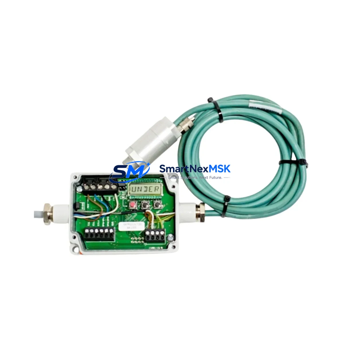
AMAT RAYMID10LTCB3 Retrofit-Ready Pyrometer Communication Module for RayMid Control Systems
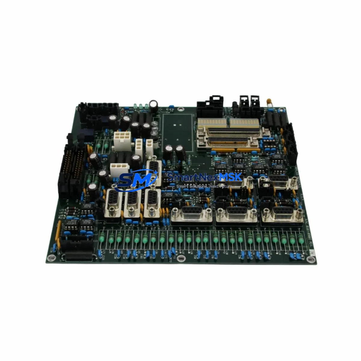
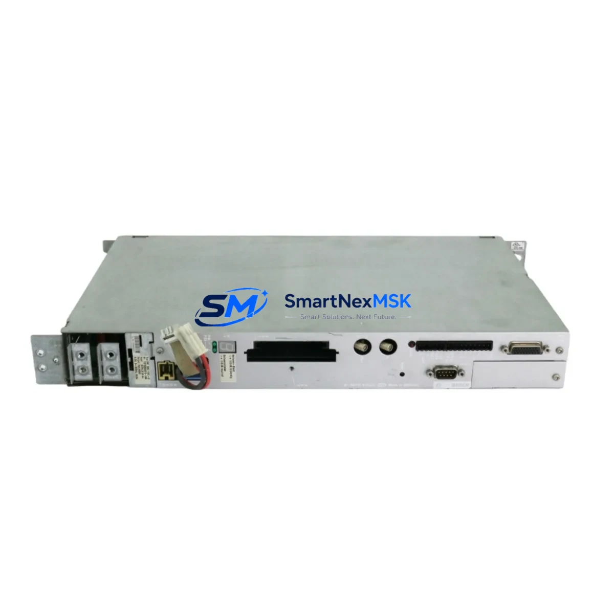
The AMAT RAYMID10LTCB3 is a retrofit-ready pyrometer communication module engineered for seamless integration into Applied Materials RayMid series temperature measurement and control systems. With cross-reference SKUs including 0190-17458, ACRTC-A, HIMV-307A, and 04876401, this module is a verified drop-in replacement for aging or discontinued components in semiconductor process equipment, CVD chambers, and advanced thermal control platforms. Whether you are executing a planned upgrade, recovering from an unplanned failure, or modernizing a legacy control cabinet, the RAYMID10LTCB3 delivers the signal integrity, communication reliability, and form-factor compatibility required for production-critical environments.
Applied Materials designed the RayMid pyrometer series to serve high-precision wafer temperature measurement applications. The RAYMID10LTCB3 functions as the communication bridge between the pyrometer sensor head and the host process controller, transmitting real-time temperature data over the system’s internal communication bus. When this module fails or reaches end-of-life, the entire temperature feedback loop is interrupted — halting process control, triggering chamber faults, and forcing unplanned downtime. Sourcing a verified replacement with confirmed firmware and hardware compatibility is therefore a time-critical priority for process engineers and maintenance teams.
Upgrade Compatibility Table
| Parameter | Details |
|---|---|
| Primary SKU | RAYMID10LTCB3 |
| Cross-Reference SKUs | 0190-17458 / ACRTC-A / HIMV-307A / 04876401 / 16692 |
| OEM Brand | Applied Materials (AMAT) |
| Compatible Series | RayMid Pyrometer Series |
| Module Function | Pyrometer Communication Interface |
| Communication Interface | RS-232 / RS-485 / Proprietary AMAT Bus (verify per chamber revision) |
| Mounting / Form Factor | Direct backplane or DIN-rail mount per original installation |
| Power Requirements | Verify 24 VDC supply capacity at installation point before swap |
| Replacement Type | Drop-in hardware replacement; firmware version confirmation recommended |
| Commissioning Requirement | Address configuration, calibration offset verification, HMI tag re-mapping |
| Warranty | 12 Months from date of shipment |
| Condition | New / Refurbished (specify at order) |
| Lead Time | In-stock; same-day or next-day dispatch available |
Retrofit Planning for Existing Automation Systems
A successful RAYMID10LTCB3 retrofit begins well before the module arrives on-site. Maintenance engineers should first audit the existing RayMid installation to confirm the chamber revision level, backplane slot assignment, and the firmware version currently running on the host controller. In many AMAT CVD and RTP systems, the pyrometer communication module shares a backplane with the AMAT RAYMID10 main processor board and interfaces directly with the RayMid sensor head assembly. Confirming that the replacement module’s firmware is compatible with the installed sensor head prevents calibration drift and signal offset errors after the swap.
Terminal wiring is a frequent source of commissioning delays. Before removing the failed module, photograph and document all terminal connections, paying particular attention to the RS-485 differential pair polarity, shield grounding points, and any jumper settings on the module itself. In systems where the RAYMID10LTCB3 communicates upstream to a Siemens S7-300 or S7-400 PLC via a Profibus DP gateway, or to an Allen-Bradley ControlLogix platform via an EtherNet/IP bridge, the communication link parameters — baud rate, station address, and timeout settings — must be re-entered after module replacement. Failure to restore these parameters will result in a communication fault at the PLC level even if the pyrometer module itself is functioning correctly.
For systems that include an AMAT RAYMID power supply module in the same control cabinet, verify that the supply’s output capacity is sufficient to support the replacement module under full load. Aging power supplies in legacy cabinets sometimes operate near their rated capacity, and introducing a new module — even a direct replacement — can expose a marginal supply condition. Similarly, if the control cabinet houses an AMAT I/O expansion rack or a third-party remote I/O module on the same 24 VDC bus, a load audit is recommended before powering up the replacement.
HMI integration is another critical checkpoint. In facilities running Wonderware InTouch, FactoryTalk View, or AMAT’s proprietary process control interface, the pyrometer temperature tags are typically mapped to specific communication addresses. After replacing the RAYMID10LTCB3, confirm that the HMI tag database still resolves correctly to the new module’s address. If the module address was changed during the replacement — for example, due to a DIP switch or software address setting — the HMI tags must be updated accordingly to prevent false readings or alarm suppression.
Where the existing system includes a programming cable or USB-to-RS232 adapter for direct module configuration, ensure the cable is available on-site before beginning the swap. Some AMAT RayMid modules require a direct serial connection for initial address assignment and calibration offset entry. Having the correct cable and configuration software ready eliminates a common source of extended downtime during retrofit operations.
Downtime Control During System Migration
Minimizing downtime during a RAYMID10LTCB3 replacement requires a structured pre-swap checklist and a clear rollback plan. Before taking the chamber offline, export or photograph the current process recipe parameters, pyrometer calibration offsets, and any alarm setpoints stored in the host controller. If the host PLC — whether an AMAT embedded controller, a Siemens S7 series CPU, or an Allen-Bradley Logix platform — retains pyrometer configuration in non-volatile memory, verify that a current backup exists before the swap begins.
The physical swap itself is typically completed in under 30 minutes for a trained technician familiar with the RayMid backplane layout. The extended downtime risk lies in post-swap commissioning: address configuration, communication link verification, calibration confirmation, and HMI tag validation. Preparing a commissioning checklist in advance — covering each of these steps in sequence — reduces the risk of missing a step under time pressure and allows a second technician to verify each item independently.
Where production schedules permit, a parallel test is strongly recommended: install the replacement RAYMID10LTCB3 in a spare slot or test fixture, configure it to match the production module’s settings, and verify communication and calibration before taking the production chamber offline. This approach compresses the actual chamber downtime to the physical swap and final verification steps, typically under 15 minutes. All units shipped by SMARTNEXMSK undergo pre-shipment functional testing to confirm communication interface integrity and basic signal output, reducing the risk of receiving a non-functional replacement and extending the downtime window.
Retrofit Support FAQ
Q1: Is the RAYMID10LTCB3 a direct drop-in replacement for my existing RayMid communication module?
In the majority of RayMid series installations, yes. The RAYMID10LTCB3 is form-factor and interface compatible with the standard RayMid backplane. However, we recommend confirming your chamber’s revision level and the installed firmware version before ordering. Our technical team can assist with compatibility verification based on your chamber model and existing module part number.
Q2: What commissioning steps are required after installing the replacement module?
At minimum: (1) confirm module address matches the original configuration, (2) verify communication link to the host controller is established and error-free, (3) confirm pyrometer calibration offsets are correctly entered, and (4) validate HMI temperature tags are reading correctly. For systems with Profibus or EtherNet/IP upstream communication, also verify the gateway configuration has not been disrupted by the module swap.
Q3: How do I verify wiring compatibility before installing the RAYMID10LTCB3?
Document all existing terminal connections before removing the failed module, including wire colors, terminal numbers, shield connections, and any jumper positions. Compare against the RAYMID10LTCB3 terminal diagram. Pay particular attention to RS-485 polarity (A/B differential pair) and 24 VDC supply polarity. If the original wiring documentation is unavailable, our team can provide terminal reference diagrams based on the chamber model.
Q4: What does the 12-month warranty cover?
All RAYMID10LTCB3 units supplied by SMARTNEXMSK carry a 12-month warranty from the date of shipment, covering manufacturing defects and functional failures under normal operating conditions. Each unit undergoes pre-shipment functional testing. Warranty claims are supported by our technical team with replacement dispatch typically within 48 hours of confirmed fault diagnosis. The warranty does not cover damage resulting from incorrect installation, overvoltage, or physical mishandling.
© 2026 SMARTNEXMSK. All rights reserved.
Original Source: https://smartnexmsk.com
Contact: [email protected] | +86 18259474341